什麼是包?什麼是 UML 中的包圖?

什麼是包?什麼是 UML 中的包圖?

Packages in the Unified Modeling Language are used to group elements and provide namespaces for the grouped elements. A package can contain other packages, thus providing a hierarchical organization of packages. Almost all UML elements can be grouped into packages. Thus, classes, objects, use cases, components, nodes, node instances, etc. can be organized into packages, thus making the organization of the myriad elements contained in a real-world UML model manageable.
關於序列圖你需要知道的一切

關於序列圖你需要知道的一切

UML Sequence Diagrams are interaction diagrams that detail how operations are carried out. They capture the interaction between objects in the context of a collaboration. Sequence Diagrams are time focus and they show the order of the interaction visually by using the vertical axis of the diagram to represent time what messages are sent and when.
用例圖中的四種關係類型

用例圖中的四種關係類型

In UML, relationships are connections between model elements. Use cases are also connected to each other in different kinds of relationships. The relationship between two use cases basically models the dependencies between two use cases. By reusing existing use cases using different types of relationships, the overall effort required to develop the system is reduced. Use case diagrams show use cases, actors, and the relationships between them. For example, the relationship between an actor and a use case illustrates that the actor can use a certain functionality of the business system.
“包含”和“擴展”用例

“包含”和“擴展”用例

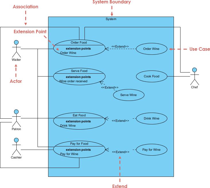
Use case relationships model the dependencies between use cases in the interaction model of the system. Although, independent use cases can adequately represent simpler systems. However, in order to represent complex or large systems, we may need to construct complex use cases with the help of dependencies between use cases. Establishing relationships between use cases allows reuse of those use cases that need to be defined over and over again, which reduces developer effort.
什麼是多重性

什麼是多重性

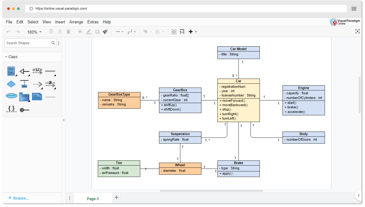
Multiplicity in class diagram should be indicated at each end of the association. This specifies the minimum and maximum number of instances that can be linked. For example, a car has 3 or 4 wheels, but each wheel belongs to exactly one car. Place multiplicity notations near the ends of an association. These symbols indicate the number of instances of one class linked to one instance of the other class.
用例圖——符號指南

用例圖——符號指南

A use case diagram is a Unified Modeling Language (UML) diagram for requirements elicitation. Use case diagrams provide a graphical overview of the goals (modeled by use cases) that users (represented by actors) want to achieve by using the system. Use cases in a use case diagram can be organized and arranged according to their relevance, level of abstraction, and impact on the user. They can be linked to show their dependencies, include, extend, generation relationships.