


Define entry, exit, and do activity for a state
Create diagrams easily with Visual Paradigm Online. You can easily edit your own state machine diagram with our powerful diagram maker tool in the VP Online. In this video, you can see how to define entry, exit, and do activity for a state in VP Online.
What is a state machine diagram?
UML State Machine Diagrams (sometimes referred to as state diagrams, state machines, or statecharts) show the different states of an entity. State machine diagrams can also show how an entity responds to various events by changing from one state to another. A state machine diagram is a UML diagram used to model the dynamic nature of a system. State machine diagrams typically are used to describe state-dependent behavior for an object. An object responds differently to the same event depending on what state it is in. State machine diagrams are usually applied to objects but can be applied to any element that has behavior to other entities such as actors, use cases, methods, subsystems systems and etc. and they are typically used in conjunction with interaction diagrams (usually sequence diagrams).
What is a State?
Rumbaugh defines that:
“A state is an abstraction of the attribute values and links of an object. Sets of values are grouped together into a state according to properties that affect the gross behavior of the object.”
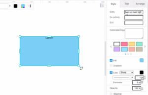
How to define entry, exit, and do activity for a state?
- When editing a state in a state machine diagram, you can select the state, then go to Format Panel, Style, to define its entry, do an activity, and exit behavior.

Tip: The diagrams maker supports a rich set of style options for all diagrams types. You can easily customize your diagrams to match your company’s brand colors and fonts or choose the color that matches your topic. Customize everything, from the fonts and colors to the position of titles and legends in a few clicks.
This post is also available in Deutsche, Español, فارسی, Français, English, Bahasa Indonesia, 日本語, Polski, Portuguese, Ру́сский, Việt Nam, 简体中文 and 繁體中文.
