


Beginner’s Guide to Component Diagrams in UML
Introduction
Unified Modeling Language (UML) is a visual language used in software engineering to model and design software systems. Component diagrams are one of the UML diagrams used to represent the high-level structure of a software system in terms of its components and their relationships. In this beginner’s guide, we will introduce you to component diagrams in UML and show you how to create them using Visual Paradigm Online, a popular online UML modeling tool with a large collection of templates.
What is a Component Diagram?
A component diagram in UML provides a high-level view of a software system’s architecture by showing the components that make up the system and their relationships. Components are modular parts of the system that encapsulate some functionality and can be independently replaceable and upgradeable. Component diagrams are useful for understanding the organization of a system and its dependencies on other components.
Key Concepts in Component Diagrams
Before we dive into creating component diagrams, let’s understand some key concepts:
- Component: A component is a modular unit of software that encapsulates some functionality. It can be a class, a module, a library, or even a physical component like a server or a database.
- Interface: An interface defines a contract that specifies the services provided or required by a component. It acts as a boundary through which components interact with each other.
- Dependency: A dependency relationship indicates that one component relies on another component. It can be a required or provided interface dependency.
- Association: An association represents a link between two components, indicating a relationship between them. Associations can have roles and multiplicities.
- Artifact: An artifact is a physical file or software component that represents a piece of software, such as a source code file or a database script.
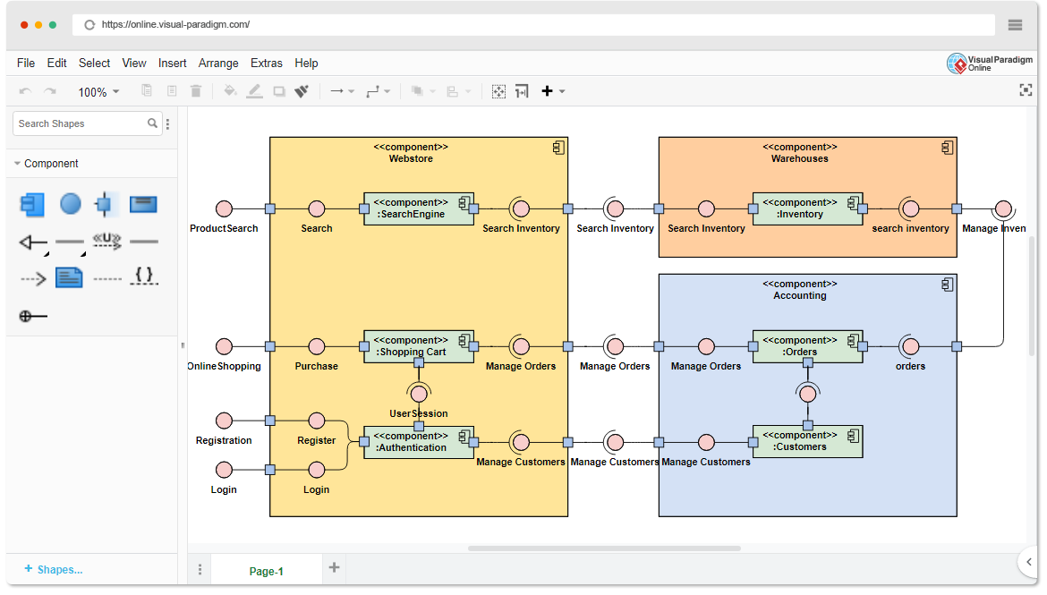
Creating Component Diagrams in Visual Paradigm Online
Visual Paradigm Online is a user-friendly online modeling tool that makes it easy to create component diagrams. Here’s how to get started:
- Sign In or Sign Up: If you don’t have an account, sign up for a free Visual Paradigm Online account.
- Create a New Project: After signing in, create a new project for your component diagram.
- Select Component Diagram: In your project, select “Create Diagram” and choose “Component Diagram” from the list of diagram types.
- Add Components: Drag and drop components from the toolbox onto the diagram canvas. Name and define the properties of each component.
- Define Interfaces: Create interfaces by adding them to the components. Specify the operations provided or required by each interface.
- Establish Dependencies: Use dependency arrows to show relationships between components. Indicate whether the dependency is for a required or provided interface.
- Add Associations: If components have associations, use association connectors to represent them on the diagram. Define roles and multiplicities as needed.
- Include Artifacts: If your system includes physical files or external components, add artifacts to the diagram and link them to the relevant components.
- Documentation: Don’t forget to document your diagram by adding text descriptions and annotations as needed to clarify the system’s architecture.
Learning by Examples
Visual Paradigm Online provides a vast collection of UML templates, including component diagram templates. To learn more about creating component diagrams and to explore real-world examples, you can
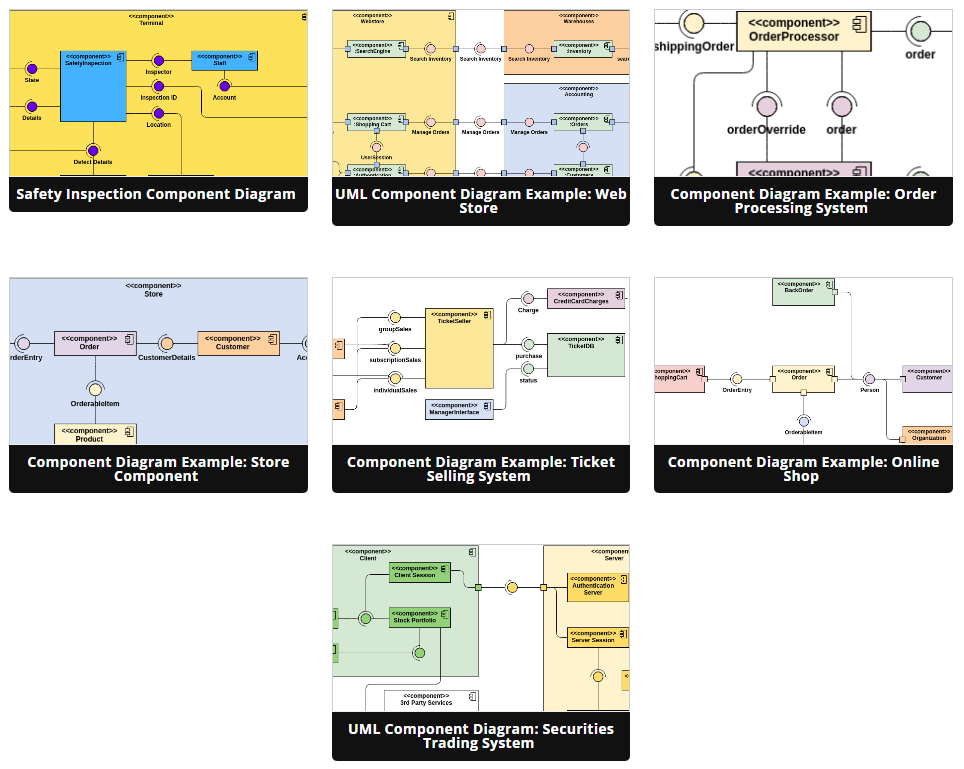
- Browse Templates: In Visual Paradigm Online, browse the template library to find pre-built component diagram templates.
- Customize Templates: Start with a template that matches your project’s domain and customize it to meet your specific requirements.
- Learn from Examples: Analyze the components, interfaces, dependencies, and associations in the template diagrams to understand how different systems are structured.
- Experiment: Create your own component diagrams from scratch, following the patterns and best practices you’ve learned from the templates.
Conclusion
Component diagrams in UML are valuable tools for visualizing the high-level architecture of software systems. With the help of Visual Paradigm Online and its extensive template library, you can quickly grasp the concepts and create effective component diagrams for your own projects. Remember that practice and experimentation are key to becoming proficient in using component diagrams to design and communicate software architectures.
This post is also available in Deutsche, Español, فارسی, Français, English, Bahasa Indonesia, 日本語, Polski, Portuguese, Ру́сский, Việt Nam, 简体中文 and 繁體中文.
