


Beginner’s Guide to Robustness Diagrams with Visual Paradigm Online
Introduction
Robustness diagrams are a valuable tool in software engineering for modeling the interactions between different parts of a software system. They help you understand how different components or objects in a system collaborate to achieve specific functionality. In this beginner’s guide, we will introduce you to robustness diagrams and show you how to create them using Visual Paradigm Online, a powerful online diagramming tool.
What is a Robustness Diagram?
A robustness diagram is a dynamic model used to illustrate the interaction between external actors (e.g., users, other systems, or devices) and the internal components or objects of a software system. It focuses on the high-level functionality of the system and helps you visualize how the system responds to external stimuli.
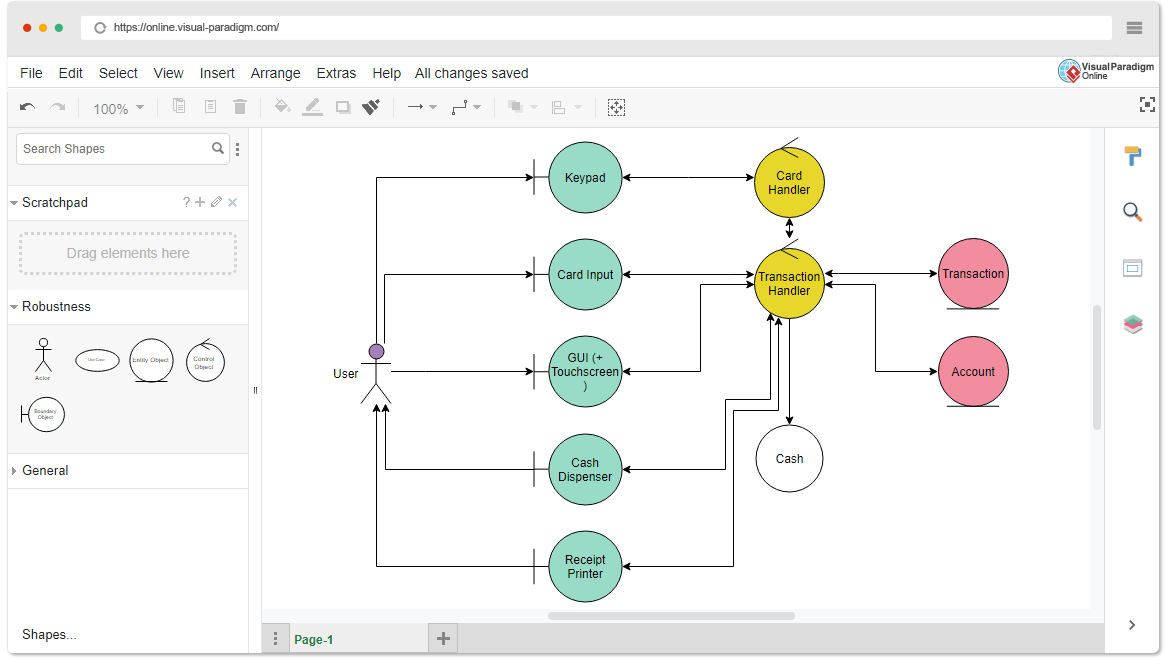
Key elements of a robustness diagram include:
- Actors: These represent external entities interacting with the system. Actors can be users, external systems, or any element outside the system boundary.
- Objects: Robustness diagrams typically involve three types of objects:
- Entity Objects: Represent real-world data or information that the system stores and manipulates.
- Control Objects: Represent the logic and control flow within the system, often corresponding to the use cases or operations.
- Boundary Objects: Represent the interfaces between the system and external actors, handling input and output.
- Associations: Arrows or lines connecting actors and objects, indicating the interactions or relationships between them.
Creating Robustness Diagrams with Visual Paradigm Online
Visual Paradigm Online is an excellent tool for creating robustness diagrams. Follow these steps to create your own robustness diagram:
- Sign In or Create an Account: If you don’t already have an account, sign up for Visual Paradigm Online or log in if you have an existing account.
- Start a New Project:
- Click on “New Project.”
- Select “Use Case & Requirements” under the “Software Engineering” section.
- Create a Use Case Diagram:
- Once you’re inside the project, click on the “+ Diagram” button.
- Select “Use Case Diagram” from the options.
- Add Actors and Objects:
- On the left-hand sidebar, find the “Actor” and “Object” icons, and drag them onto your diagram.
- Rename actors and objects to represent external entities and the various types of objects (entity, control, boundary).
- Connect Actors and Objects:
- Use the “Association” arrow (found on the left sidebar) to connect actors and objects.
- This arrow represents the interaction between actors and objects.
- Define Relationships:
- Double-click on the associations to specify the type of interaction or relationship between actors and objects.
- System Boundary:
- Optionally, you can draw a rectangle around the actors, entity objects, control objects, and boundary objects to indicate the system boundary.
- Save Your Diagram:
- Click the “Save” button to save your work.
Learn by Examples with Templates
Visual Paradigm Online offers a large collection of templates for various types of diagrams, including robustness diagrams. To learn more and gain inspiration, you can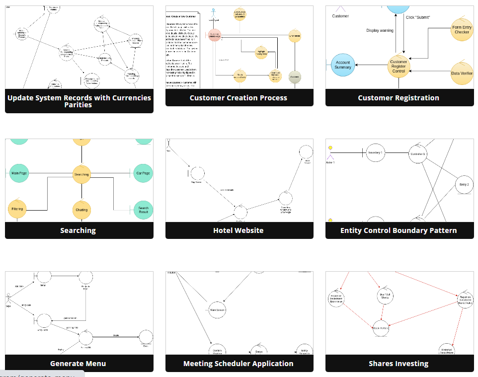
- Access Templates:
- From the main dashboard, click on “Templates” to explore a wide range of pre-made templates.
- Select a Robustness Diagram Template:
- Browse through the available templates or use the search bar to find a robustness diagram template.
- Customize and Learn:
- Open a template to study its structure and customize it for your own project.
- You can modify actors, entity objects, control objects, boundary objects, and associations to match your specific system.
Conclusion
Robustness diagrams are a powerful tool for understanding how a software system interacts with external actors and internal objects of various types. Visual Paradigm Online makes it easy for beginners to create robustness diagrams and offers a wealth of templates to learn from. Start using robustness diagrams to improve your software design and communication with stakeholders. Happy modeling!
This post is also available in Deutsche, Español, فارسی, Français, English, Bahasa Indonesia, 日本語, Polski, Portuguese, Ру́сский, Việt Nam, 简体中文 and 繁體中文.
