


Beginner’s Guide to SysML Internal Block Diagrams
Introduction
SysML, or the Systems Modeling Language, is a powerful tool used for modeling complex systems. Among its various diagram types, the SysML Internal Block Diagram (IBD) is particularly useful for depicting the internal structure of a system component. In this beginner’s guide, we’ll explore what a SysML Internal Block Diagram is, its purpose, and how to create one using Visual Paradigm Online’s collection of templates.
What is a SysML Internal Block Diagram?
Block: In SysML, a Block is a fundamental building block that represents a system component. Blocks are typically depicted as rectangles with the keyword “«block»” inside. These Blocks encapsulate their contents, which can include Properties, Behaviors, and Constraints. Behaviors can take various forms, such as Operations, Signals, and State Machines. Blocks also support Interfaces, which allow them to interact with other components. Ports are the unique points where Block Interfaces can be attached and connected.
Blocks are versatile and can represent a wide range of components, including software, hardware, mechanical parts, and even entities like people or organizations.
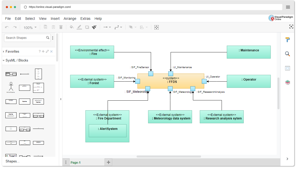
Internal Block Diagram (IBD): An Internal Block Diagram is a static structural diagram associated with a specific Block. Its primary purpose is to reveal the internal structure of the encapsulated Block. In essence, an IBD offers a “white-box” perspective of a Block, showing its structural elements like Parts, Properties, Connectors, Ports, and Interfaces. It contrasts with the “black-box” view, which conceals the internal details of the Block.
One of the key features of IBDs is the ability to recursively decompose Blocks into Parts. This decomposition alternates between Block Definition Diagrams (BDDs) and IBDs. Behaviors, whether encapsulated by Blocks or allocated to them via Dependencies, can also be illustrated in IBDs.
SysML allows you to use Constraint Blocks to mathematically constrain Blocks, enabling the creation of parametric diagrams that can be simulated.
Compare and Contrast
SysML Internal Block Diagrams differ from other diagram types and modeling languages:
- UML 2 Class and Component Diagrams: While UML diagrams often focus on object-oriented concepts, SysML IBDs emphasize the internal structure of system components and how they connect. UML class diagrams are more about defining classes and their relationships, whereas IBDs delve into a system’s structural details.
- SA/SD System Context & Structure Chart Diagrams: System Architecture/Structured Analysis and Design (SA/SD) diagrams focus on high-level system context and structure. SysML IBDs offer a finer-grained view of a component’s internal structure and connectivity.
- IDEF IDEF1X Diagrams: IDEF (Integrated Definition) diagrams are used for various modeling purposes, including data modeling. SysML IBDs concentrate on the structural aspects of system components rather than data modeling.
Purpose of SysML Internal Block Diagrams
The primary purpose of SysML Internal Block Diagrams (IBDs) is to visually represent the encapsulated structural contents of Blocks. By doing so, IBDs enable a detailed examination of a system’s internal architecture, including its Parts, Properties, Connectors, Ports, and Interfaces. These diagrams facilitate the recursive decomposition of Blocks and support Interface Based Design techniques.
When used correctly, in conjunction with Block Definition Diagrams (BDDs), IBDs allow for scalable and mathematically simulatable modeling. This means that you can analyze and simulate the behavior of the system, considering its internal structure and interactions.
Learning by Example with Visual Paradigm Online
Visual Paradigm Online offers some templates to help you get started with SysML Internal Block Diagrams. These templates provide pre-designed elements and structures that you can customize to suit your modeling needs. To learn SysML IBDs effectively, follow these steps
- Access Visual Paradigm Online: Start by accessing Visual Paradigm Online, a user-friendly online modeling tool.
- Select a SysML IBD Template: Browse the template library and choose a SysML Internal Block Diagram template that aligns with your modeling project.
- Customize the Template: Use the template as a starting point. Add Blocks, Parts, Properties, Connectors, Ports, and Interfaces to represent your system’s internal structure. Connect them as needed to show relationships.
- Add Behaviors: If your system includes behaviors like Operations, Signals, or State Machines, incorporate them into your IBD.
- Recursive Decomposition: If your system is complex, consider decomposing Blocks into Parts and create sub-diagrams as necessary to maintain clarity.
- Constraint Blocks: If applicable, use Constraint Blocks to mathematically constrain your Blocks and create parametric diagrams.
- Simulation: Visual Paradigm Online allows you to simulate the behavior of your system, taking into account the internal structure you’ve defined in your IBD.
- Documentation: Finally, remember to document your IBD effectively, adding descriptions, annotations, and notes where necessary to make your model clear and understandable to others.
By following these steps and leveraging the Visual Paradigm Online templates, you can learn SysML Internal Block Diagrams through practical examples and create comprehensive models of your system’s internal architecture.
Conclusion
SysML Internal Block Diagrams are a valuable tool for modeling and understanding the internal structure of system components. They enable a detailed examination of how different parts of a system interact and can be recursively decomposed for scalable modeling. Visual Paradigm Online’s templates provide an excellent starting point for learning and applying this essential SysML diagram type.
This post is also available in Deutsche, Español, فارسی, Français, English, Bahasa Indonesia, 日本語, Polski, Portuguese, Ру́сский, Việt Nam, 简体中文 and 繁體中文.
