


Beginner’s Guide to SysML Parametric Diagrams
Introduction
SysML (Systems Modeling Language) is a powerful tool for designing complex systems, and Parametric Diagrams are a valuable component of SysML that help model and analyze mathematical relationships within a system. In this beginner’s guide, we will explore the fundamentals of Parametric Diagrams, their significance, and how to create them using visual modeling tools like Visual Paradigm Online, which offers a collection of templates to simplify the process.
What are Parametric Diagrams?
Parametric Diagrams in SysML are graphical representations used to illustrate mathematical relationships, constraints, and equations among various components or elements of a system. These diagrams are particularly useful for modeling and analyzing performance constraints and dependencies within a system.
Prerequisites
Before you can start working with Parametric Diagrams, ensure that you are using the SysML profile for your project, as Parametric Diagrams are specific to this profile.
General Uses of Parametric Diagrams
Parametric Diagrams serve several important purposes in system design:
- Objective Analysis of Functions: They help in identifying and visualizing the relationships between different functions or components within a system, allowing for a comprehensive analysis.
- Measurement of Effectiveness: Parametric Diagrams enable you to measure the effectiveness of various system elements by modeling their dependencies and constraints mathematically.
- Clarification of Relationships: They provide a clear visual representation of how one variable or parameter relates to another, making it easier to understand complex system behaviors.
Creating Parametric Diagrams
Parametric Diagrams are not standalone entities; they are created using model elements known as constraint blocks. These blocks define generic or basic mathematical formulas that describe the relationships between system components. Here’s a step-by-step guide to creating Parametric Diagrams:
1. Define Constraint Blocks
Constraint blocks are essential building blocks for Parametric Diagrams. They encapsulate mathematical equations and relationships. To create constraint blocks:
- Access your modeling tool (e.g., Visual Paradigm Online).
- Navigate to your project and choose the SysML profile.
- Within a Block Definition Diagram, create constraint blocks that represent mathematical formulas relevant to your system.
2. Create a Parametric Diagram
Once you have defined the necessary constraint blocks, you can proceed to create a Parametric Diagram:
- Within your project, navigate to the diagram creation menu.
- Select “Parametric Diagram” from the available diagram types.
- Begin adding constraint properties and connecting them to the appropriate constraint blocks, creating the mathematical relationships within your system.
3. Add Input Parameters
In a Parametric Diagram, you often need to define input parameters or values that are fed into the equations represented by constraint blocks. These inputs will allow you to perform calculations and analyze system behavior under different conditions.
4. Model the Mathematical Relationships
Connect the constraint properties, constraint blocks, and input parameters to represent the mathematical relationships accurately. Use connectors and annotations to document your equations and constraints clearly.
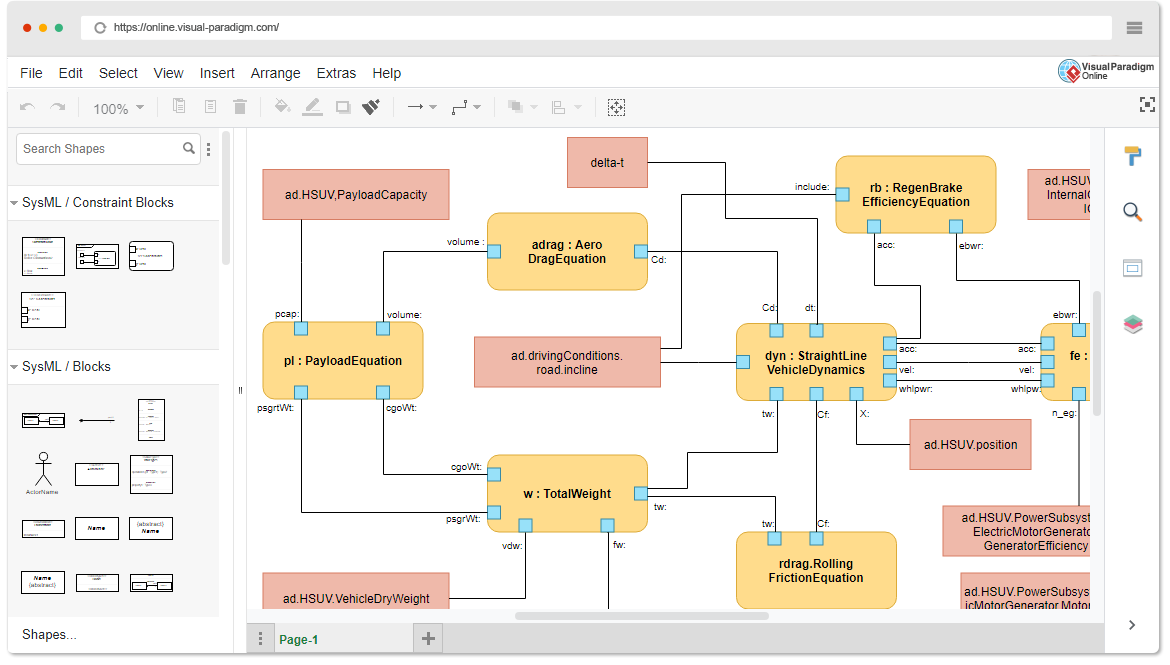
Learning by Examples with Visual Paradigm Online
Visual Paradigm Online offers some templates that can assist you in creating Parametric Diagrams. You can start by exploring these templates and modifying them to suit your specific system design needs. Learning by examples is an effective way to grasp the concepts and techniques of Parametric Diagrams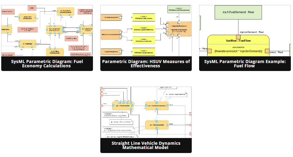
Conclusion
SysML Parametric Diagrams are invaluable tools for modeling and analyzing mathematical relationships within complex systems. By following the steps outlined in this guide and utilizing visual modeling tools like Visual Paradigm Online, you can effectively design and analyze systems with confidence and precision.
This post is also available in Deutsche, Español, فارسی, Français, English, Bahasa Indonesia, 日本語, Polski, Portuguese, Ру́сский, Việt Nam, 简体中文 and 繁體中文.
