Use Case Diagram Tutorial

Use Case Diagram Tutorial

Introduction A use case diagram is a graphical representation of the interactions between users (actors) and a system. It helps to identify the system's functional requirements by illustrating the different ways users can interact with the system to achieve specific goals. This tutorial will guide you through the basics of creating and understanding use case diagrams, using the Wheels bike hire system examples on object-oriented development. What is a Use Case Diagram? A use case diagram is a type of behavioral diagram defined by the Unified Modeling Language (UML). It consists of use…continue reading →
Step-by-Step Class Diagram Tutorial Using Visual Paradigm

Step-by-Step Class Diagram Tutorial Using Visual Paradigm

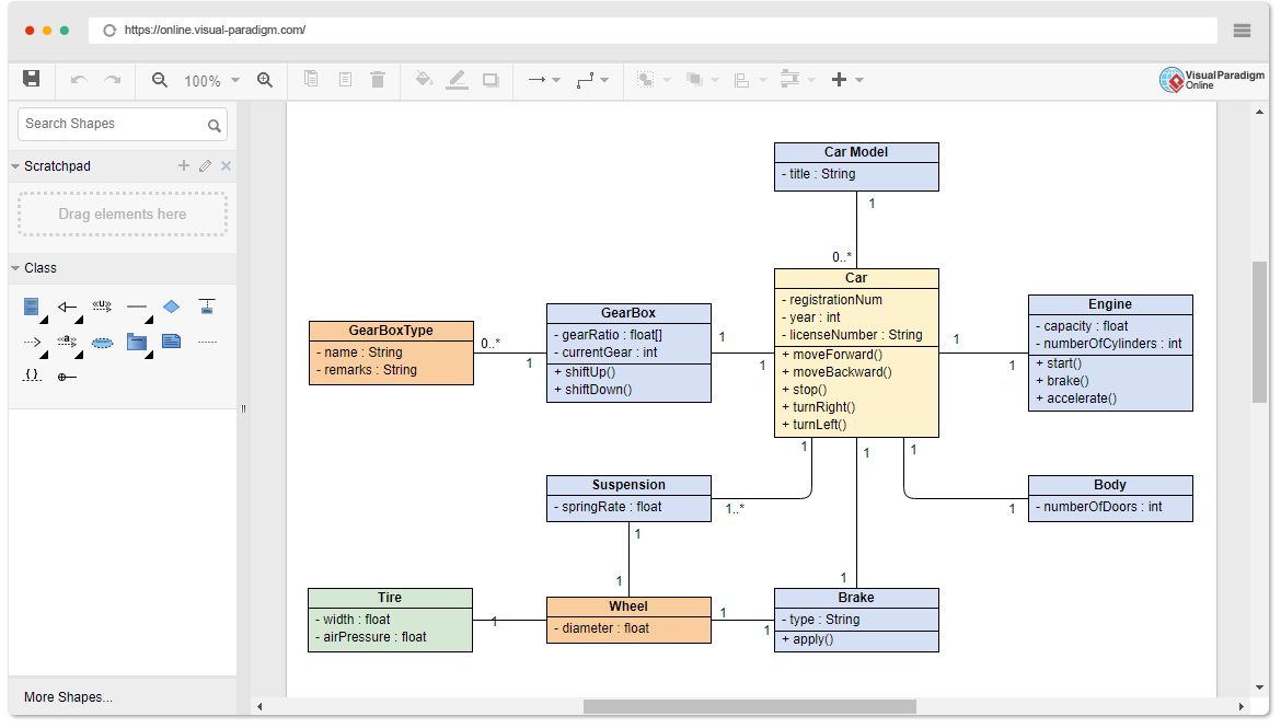
What is a Class Diagram? A class diagram is a static structure diagram in UML (Unified Modeling Language) that shows the system's classes, their attributes, methods (operations), and the relationships between objects. It is used to model the static view of an application. Why Use a Class Diagram? Visual Representation: Provides a clear visual representation of the system's structure. Communication: Helps in communicating the design of the system to stakeholders. Blueprint: Acts as a blueprint for the system's implementation. Documentation: Serves as documentation for the system's design. When to Use a Class Diagram? Design Phase: During the design…continue reading →
Visual Paradigm: A Comprehensive UML Modeling Solution

Visual Paradigm: A Comprehensive UML Modeling Solution

In the dynamic world of software development, having a powerful and user-friendly UML modeling tool is crucial for designing, communicating, and documenting complex systems. Among the leading options in the market, Visual Paradigm stands out as a comprehensive and versatile solution that caters to the needs of professionals, students, and hobbyists alike. Visual Paradigm is a robust UML modeling tool that offers a wide range of features to support the entire software development lifecycle. From creating UML diagrams to reverse engineering code, the tool provides a seamless and intuitive user experience. One of the standout features of Visual…continue reading →
UML Building Blocks and Diagrams (UML 2.6)

UML Building Blocks and Diagrams (UML 2.6)

UML (Unified Modeling Language) is a standard language for describing the design of software systems. As UML describes real-time systems, it is important to create a conceptual model and gradually build upon it. The conceptual model of UML can be mastered by learning the following three major elements: UML Building Blocks Rules to connect the building blocks Common mechanisms of UML UML Building Blocks The building blocks of UML can be defined as: Things Relationships Diagrams Things Things are the most important building blocks of UML. They can be further classified into: Structural…continue reading →
ATM System Visual Modeling: A Case Study

ATM System UML Visual Modeling: A Case Study

Introduction Automated Teller Machines (ATMs) have become an integral part of modern banking and financial services. As the demand for convenient and accessible banking solutions continues to grow, the need for robust and efficient ATM systems has become more critical than ever. In this case study, we will explore the visual modeling of an ATM system using the Unified Modeling Language (UML) and the Visual Paradigm for UML tool. Use Case Diagram The first step in modeling the ATM system is to identify the key actors and their interactions with the system. The…continue reading →