


Everything you need to know about sequence diagrams
UML Sequence Diagrams are interaction diagrams that detail how operations are carried out. They capture the interaction between objects in the context of a collaboration. Sequence Diagrams are time focus and they show the order of the interaction visually by using the vertical axis of the diagram to represent time what messages are sent and when.
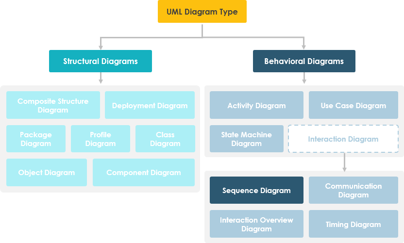
What is a sequence diagram?
A sequence diagram, also known as a sequence diagram, sequential diagram or sequential diagram, is a UML interaction diagram. It shows the dynamic collaboration between multiple objects by describing the temporal order in which messages are sent between them.
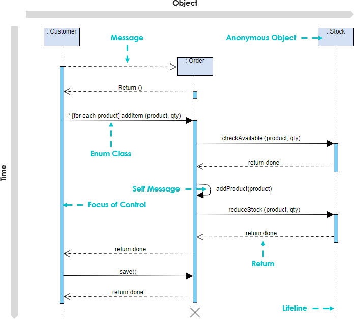
In the UML, an object in a sequence diagram is drawn as a rectangle containing the name of the object, underlined. An object can be named in one of three ways: the object name, the object name and its class, or just the class name (anonymous object). The three ways of naming an object are shown in Figure below.
The Objects of Sequence Diagram
- Show the order of interactions between objects. Model the interaction behavior as message passing, and show the interaction between objects dynamically by describing how messages are sent and received between them.
- Compared with other UML diagrams, a temporal sequence diagram places more emphasis on the chronological order of interaction behavior.
- It can visually describe the process of concurrency.
The Elements of Sequence Diagram
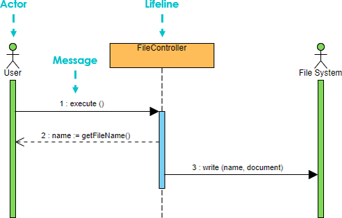
1. Actor – System actors, which can be people, machines, other systems, subsystems; used to represent in the temporal sequence diagram.
2. Object – There are three ways of naming objects:
- Includes the object name and class name, for example: live class: class, in the time series diagram, with “object: class”.
- Shows only the class name, that is, it is an anonymous object, for example: :course; in the timing diagram, with “:class”.
- Shows only the object name but not the class name, e.g.: lecturer; in the timing diagram, it is represented by “object”.
All three naming methods are available, which is the easiest for people who read the chronological chart to understand, choose which one.
3. The order of the objects
- The left and right order of the objects is not important, but in order to make a clear and neat diagram, the following two principles should be followed: put the objects with frequent interactions as close together as possible;
- Place the object that initializes the whole interaction activity at the leftmost end.
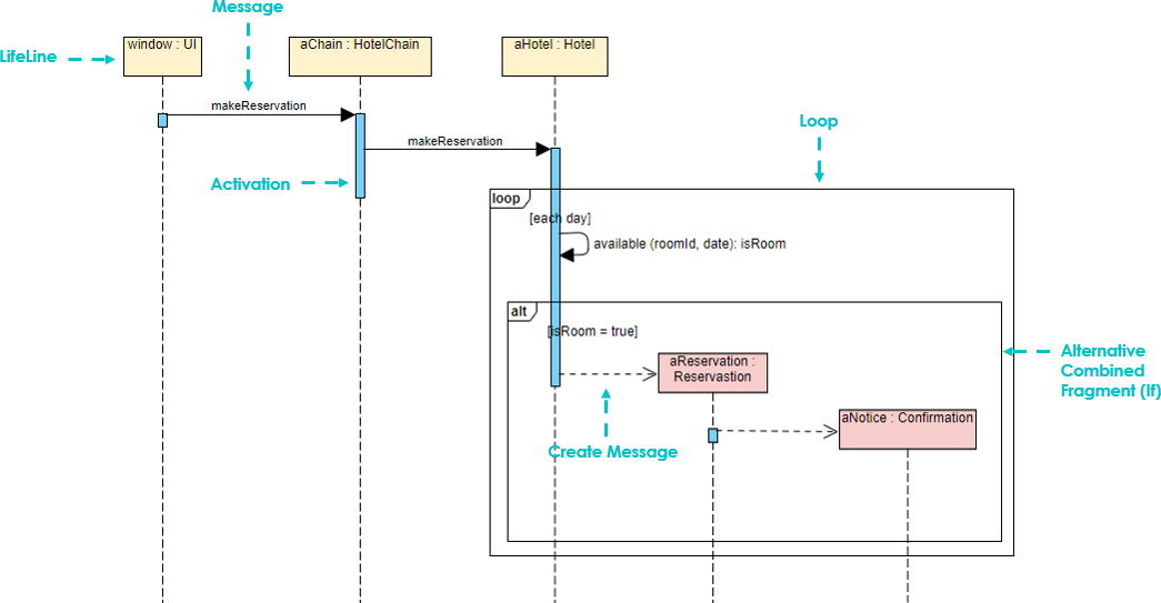
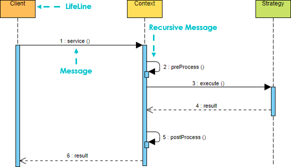
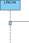
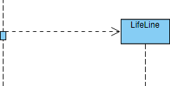
Lifeline
A dashed line extending down from the object icon in the timing diagram, indicating how long the object has existed.
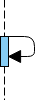
- Focus of Control (also known as the activation period) is the symbol for the time period during which the object will perform the corresponding operation. It can be interpreted as a pair of brackets { } in C semantics; represented by a small rectangle. It represents the period during which an element is performing an operation. The top and the bottom of the rectangle are aligned with the initiation and the completion time respectively.
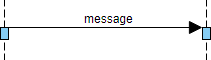
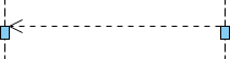
- Messages are generally classified as Synchronous Message, Asynchronous Message, and Return Message.
Note That
- The sender of a message passes control to the receiver of the message, then stops the activity and waits for the receiver of the message to give up or return control which is used to indicate synchronization.
- The sender of a message passes the signal to the receiver of the message via the message and then continues its activity without waiting for the receiver to return the message or control. The receiver and sender of an asynchronous message are working concurrently.
- Return message indicates a return from a procedure call.
Creation and Destruction Messages
Participants do not necessarily live for the entire duration of a sequence diagram’s interaction. Participants can be created and destroyed according to the messages that are being passed.
A constructor message creates its receiver. The sender that already exist at the start of the interaction are placed at the top of the diagram. Targets that are created during the interaction by a constructor call are automatically placed further down the diagram.
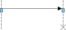
A destructor message destroys its receiver. There are other ways to indicate that a target is destroyed during an interaction. Only when a target’s destruction is set to ‘after destructor’ do you have to use a destructor.
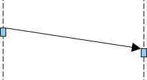
Non instantaneous message
Messages are often considered to be instantaneous, thus, the time it takes to arrive at the receiver is negligible. The messages are drawn as a horizontal arrow. To indicate that it takes a certain while before the receiver actually receives a message, a slanted arrow is used.
Combination fragments
A sequence fragment is represented as a box called a combined fragment, which encloses a part of the interaction in the sequence graph. The fragment operator (in the upper left corner) indicates the type of the fragment. Interactive fragments allow you to group related messages in a sequence diagram. Various predefined fragment types are available, allowing you to specify alternate results, parallel messages, or loops.
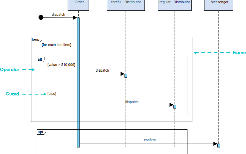
The fragment in the sequence diagram are rectangular frames drawn over a portion of the diagram. They represent the conditional structure that affects the flow of messages. These frames are called combined fragments in the UML specification, and the containers are called interaction operands. Frames are labeled in the upper left corner. This label is referred to as the interaction operator in UML.
Example – placing an order scenario
A ship member who wants to place an order online. The ordered items will be sent to the member by courier or regular mail, depending on her membership status (VIP, regular member). If the member selects the notification option in the order, the store will send a confirmation notification to the member.
Another Example: Place Order
A sequence diagram is a two-dimensional diagram with the horizontal axis representing objects and the vertical axis representing time, where messages are passed horizontally between objects and arranged vertically in chronological order. The example shows a Sequence diagram with three participating objects: Customer, Order, and the Stock. Without even knowing the notation formally, you can probably get a pretty good idea of what is going on.
- Step 1 and 2: Customer creates an order.
- Step 3: Customer add items to the order.
- Step 4, 5: Each item is checked for availability in inventory.
- Step 6, 7, 8 : If the product is available, it is added to the order.
- Step 9 return
- Step 10, 11: save and destroy order
Commonly used combination fragments
Fragment types include ref, assert, loop, break, alt, opt and neg, ref, sd.
| Operator | Meaning |
| alt | Alternative multiple fragments: only the one whose condition is true will execute. |
| opt | Optional: the fragment executes only if the supplied condition is true. Equivalent to an alt only with one trace. |
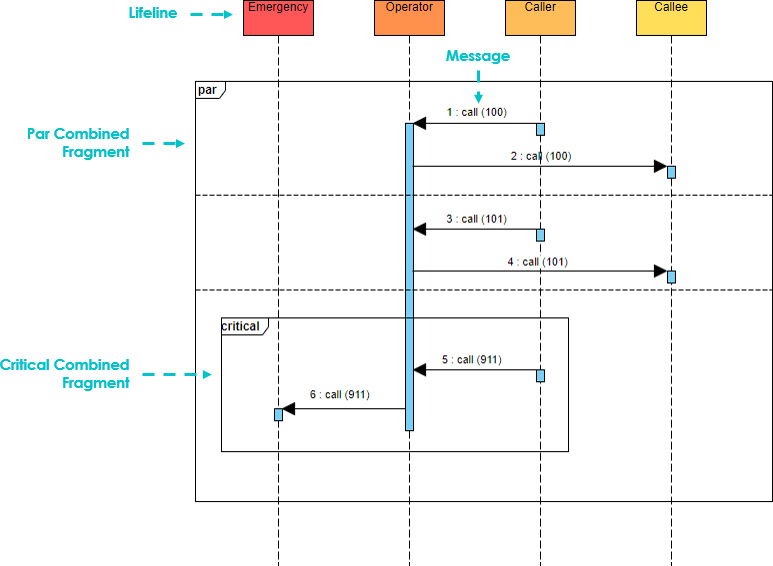
| par | Parallel: each fragment is run in parallel. |
| loop | Loop: the fragment may execute multiple times, and the guard indicates the basis of iteration. |
| critical | Critical region: the fragment can have only one thread executing it at once. |
| neg | Negative: the fragment shows an invalid interaction. |
| ref | Reference: refers to an interaction defined on another diagram. The frame is drawn to cover the lifelines involved in the interaction. You can define parameters and a return value. |
| sd | Sequence diagram: used to surround an entire sequence diagram. |
Note That:
- It is possible to combine frames in order to capture, e.g., loops or branches.
- Combined fragment keywords: alt, opt, break, par, seq, strict, neg, critical, ignore, consider, assert and loop.
- Constraints are usually used to show timing constraints on messages. They can apply to the timing of one message or intervals between messages.
Examples of Combined Fragments
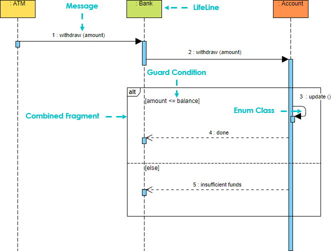
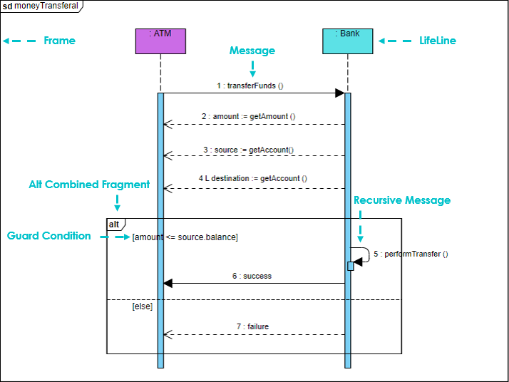
(1) Choice (Alt) – An alternative fragment provides several guarded alternative fragments (separated by interaction operands), i.e. used to specify mutually exclusive choices between two or more message sequences, equivalent to the classic if..else…:
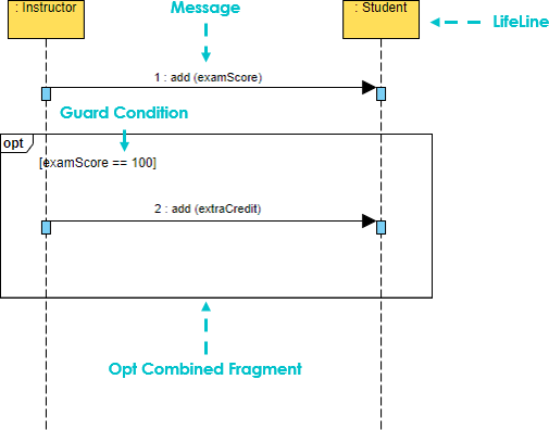
(2) Option (Opt) – Contains a sequence of possible occurrences or non-occurrence which means that an optional fragment is only executed if some guard condition is true:
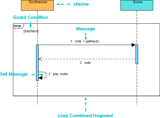
(3) Loop (Loop) – A loop allows a fragment to be repeated until some guard condition becomes false:
Break
A break allows an enclosing loop to be escaped when some guard becomes true:
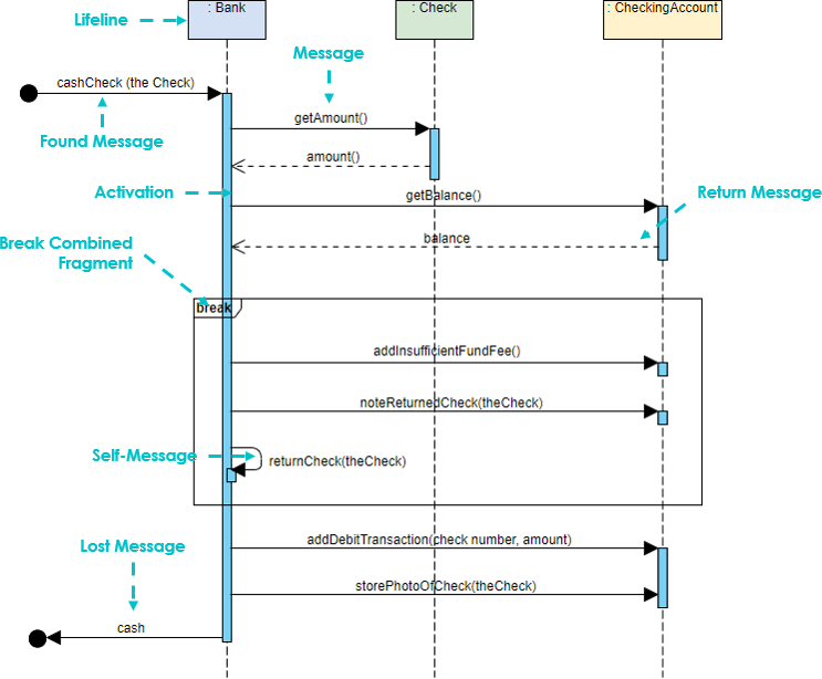
Breaks are most commonly used to model exception handling. This sequence diagram example uses a break combination fragment because it treats the balance < amount condition as an exception instead of as an alternative flow. To read this example, we start at the top left corner of the sequence and read down. When the sequence gets to the return value “balance,” it checks to see if the balance is less than the amount. If the balance is not less than the amount, the next message sent is the addDebitTransaction message, and the sequence continues as normal.
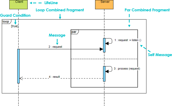
Parallel
A parallel fragment allows multiple interactions to run in parallel:
Frames
A frame provides a way to encapsulate a sequence diagram.
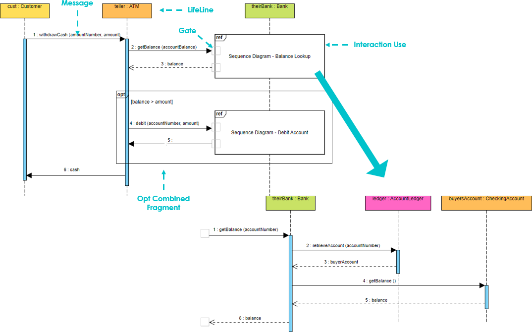
Reference (Ref)
A frame can be referenced in another sequence diagram:
Protocols
Collaborations
Scenarios
Signals and Receptions
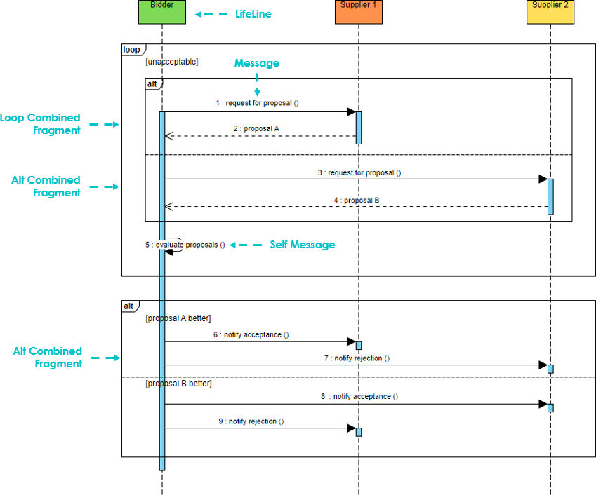
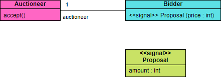
An auctioneer broadcasts a proposed price for an item to a crowded room of anxious bidders. When a bidder hears the proposal he decides to accept the price or not.
In an automated auction, how will the auctioneer broadcast the proposal? An object may have designated operations that should automatically be called if certain types of broadcast signals are received. These methods are called receptions. Signals are a special kind of class. The name of the reception usually matches the name of the signal. Receptions are shown in a separate compartment:
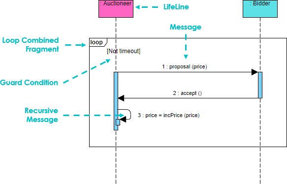
In a sequence diagram we can represent a signal as an asynchronous signal, and the reception as a reception invocation:
Critical
Other Fragment Types
- Strict
- Assert
- Consider
- Ignore
- Region
- Neg
Sequence Diagram Notation Summary
| Notation Description | Visual Representation |
|---|---|
Actor
Note that:
|
 |
Lifeline
|
 |
Activations
|
|
Call Message
|
 |
Return Message
|
 |
Self Message
|
 |
Recursive Message
|
 |
Create Message
|
 |
Destroy Message
|
 |
Duration Message
|
 |
| Note
A note (comment) gives the ability to attach various remarks to elements. A comment carries no semantic force, but may contain information that is useful to a modeler. |
 |
This post is also available in Deutsche, Español, فارسی, Français, English, Bahasa Indonesia, 日本語, Polski, Portuguese, Ру́сский, Việt Nam, 简体中文 and 繁體中文.
