


Exploring Visual Paradigm Online Diagramming Tool: A Comprehensive Guide to System Modeling Diagrams
Introduction
Visual Paradigm Online is a cloud-based diagramming tool that offers a comprehensive set of features for visual modeling and development of software and hardware systems. It provides an intuitive interface and an extensive collection of pre-built templates and shapes that make it easy to create professional-quality diagrams for various purposes.
With Visual Paradigm Online, users can create a wide range of diagrams dedicated to software and hardware modeling and development, including UML diagrams, data flow diagrams, deployment diagrams, activity diagrams, and more. These diagrams enable users to visualize and understand the structure, behavior, and functionality of the systems they are working on, making it easier to design, develop, and test software applications and hardware systems.
Visual Paradigm Online also offers collaboration features that allow users to work together on diagrams in real-time, making it easy to share ideas, exchange feedback, and make changes quickly. Users can share their diagrams with others, get feedback and comments, and track changes to ensure everyone is on the same page.
Visual Paradigm is a comprehensive diagramming tool that provides support for a wide range of diagram types, each with its unique purpose and benefits. In this article, we will introduce and describe each of these diagram types.
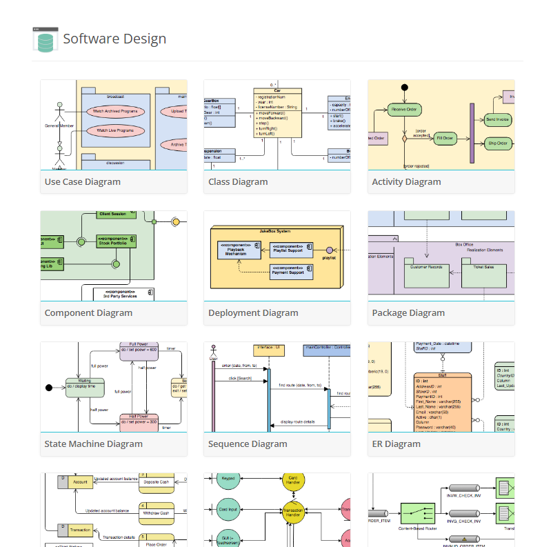
- Use Case Diagram:
Use case diagrams are used to model the interactions between actors and the system under development. They help identify the requirements of the system and provide a high-level view of the system’s functionality.
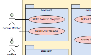
- Class Diagram:
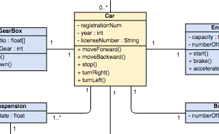
Class diagrams are used to model the static structure of a system. They show the classes, interfaces, and relationships between them, such as inheritance and association. Class diagrams are useful for understanding the architecture of the system and its components. - Activity Diagram:
Activity diagrams are used to model workflows and business processes in a system. They show the activities and actions involved in a process and the order in which they occur. Activity diagrams are useful for understanding the flow of data and control in a system and for identifying areas for optimization. - Component Diagram:
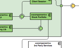
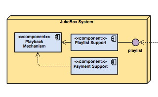
Component diagrams are used to model the components and their relationships in a system. They show how the components interact with each other to provide the system’s functionality. Component diagrams are useful for understanding the system’s architecture and for identifying opportunities for component reuse.
- Deployment Diagram:
A Deployment Diagram in Visual Paradigm is a type of UML diagram that models the physical deployment of software components to hardware nodes, such as servers or clients. The diagram illustrates the relationships between the software components and the hardware nodes they are deployed on, including the communication paths and protocols used between them. It is a valuable tool for understanding the architecture of a system and can help ensure the proper deployment of software components to hardware nodes.
- Package Diagram
Package diagrams are used to organize and manage the system’s components into packages. They show the relationships between the packages and the dependencies between them. Package diagrams are useful for organizing and managing large-scale systems and for identifying areas for component reuse - State Machine Diagram:
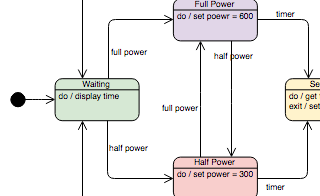
State machine diagrams are used to model the behavior of a system or component. They show the states and transitions between them, as well as the events that trigger those transitions. State machine diagrams are useful for understanding the behavior of complex systems and for designing control systems.
- Sequence Diagram:
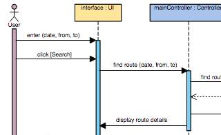
Sequence diagrams are used to model the interactions between objects or components in a system. They show the messages exchanged between objects and the order in which they are exchanged. Sequence diagrams are useful for understanding the behavior of a system and for testing purposes. - ER Diagram:
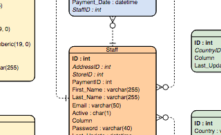
ER diagrams are used to model the relationships between entities in a database. They show the relationships between tables and the attributes of those tables. ER diagrams are useful for understanding the data architecture of a system and for identifying areas for optimization.
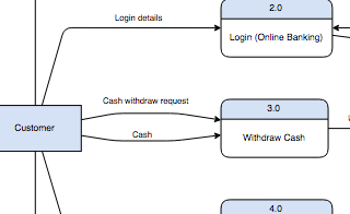
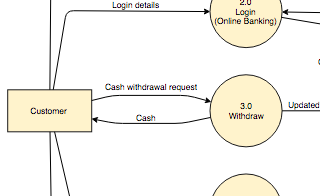
- Data Flow Diagram:
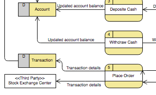 Data flow diagrams are used to model the flow of data through a system. They show the data inputs, outputs, and processes involved in a system. Data flow diagrams are useful for understanding the data architecture of a system and for identifying potential bottlenecks and performance issues.
 - Robustness Diagram:
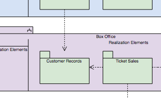
 Robustness diagrams are used to model the system’s behavior from the user’s perspective. They show the system’s objects and their interactions with the user. Robustness diagrams are useful for understanding the system’s requirements and for identifying areas for optimization.
 - Enterprise Integration Patterns:
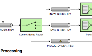
Enterprise integration patterns are used to model the integration of different systems within an organization. They show the patterns and techniques used to integrate systems, such as messaging and mediation. Enterprise integration patterns are useful for understanding the integration architecture of a system and for identifying areas for optimization. - Requirement Diagram:
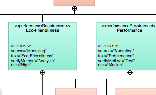
Requirement diagrams are used to model the system’s requirements. They show the requirements and the relationships between them. Requirement diagrams are useful for organizing and managing the system’s requirements and for ensuring that they are complete and consistent. - Block Definition Diagram:
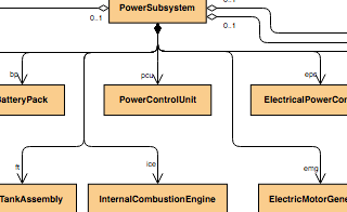
Block definition diagrams are used to model the components and their properties in a system - Parametric Diagram:
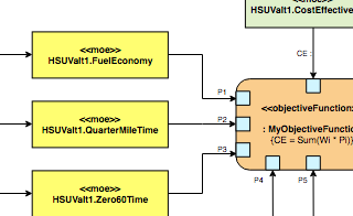
Parametric diagrams are used to model the quantitative relationships between system components. They show the parameters and their values, as well as the relationships between them. Parametric diagrams are useful for analyzing the performance and reliability of a system and for identifying areas for optimization. - Internal Block Diagram:
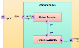
Internal block diagrams are used to model the internal structure of a system component. They show the component’s parts and their relationships, as well as the interfaces between them. Internal block diagrams are useful for understanding the system’s internal architecture and for identifying opportunities for component reuse. - C4 Model:
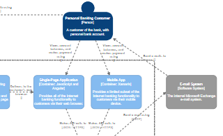
C4 models are used to model the architecture of software systems. They show the system’s components and their relationships at different levels of abstraction, from system context to component level. C4 models are useful for understanding the system’s architecture and for communicating that architecture to stakeholders. - Gane Sarson Diagram:
Gane Sarson diagrams are used to model the processes involved in a system. They show the processes, inputs, outputs, and data flows involved in a system. Gane Sarson diagrams are useful for understanding the processes involved in a system and for identifying potential bottlenecks and performance issues.
- Yourdon and Coad:
Yourdon and Coad diagrams are used to model the behavior of a system or component. They show the processes involved in a system and the relationships between them. Yourdon and Coad diagrams are useful for understanding the behavior of complex systems and for designing control systems.
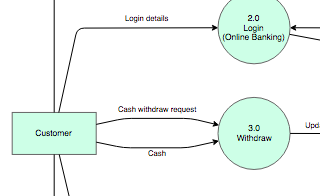
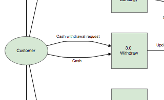
- Yourdon DeMarco DFD:
Yourdon DeMarco data flow diagrams are used to model the data flow through a system. They show the data inputs, outputs, and processes involved in a system. Yourdon DeMarco data flow diagrams are useful for understanding the data architecture of a system and for identifying potential bottlenecks and performance issues. - SSADM DFD:
 Structured Systems Analysis and Design Method data flow diagrams are used to model the data flow through a system. They show the data inputs, outputs, and processes involved in a system, as well as the relationships between them. SSADM data flow diagrams are useful for understanding the data architecture of a system and for identifying potential bottlenecks and performance issues.
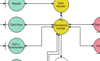
 - Hexagonal Architecture Diagram:
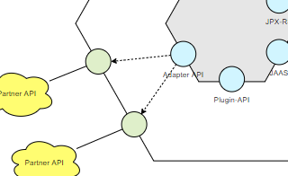
Hexagonal architecture diagrams are used to model the architecture of software systems. They show the system’s components and their relationships in a hexagonal pattern, with the system’s core components in the center and its external interfaces on the outside. Hexagonal architecture diagrams are useful for understanding the system’s architecture and for designing highly modular systems.
Visual Paradigm is a comprehensive diagramming tool that provides support for all of these diagram types and more. Its intuitive interface, powerful features, and wide range of templates and examples make it the preferred diagramming tool for developers, architects, and designers. With Visual Paradigm, you can easily create, edit, and share your diagrams, collaborate with team members, and integrate with other tools and systems. Whether you are designing a new system or optimizing an existing one, Visual Paradigm has the tools and features you need to succeed.
This post is also available in Deutsche, Español, فارسی, Français, English, Bahasa Indonesia, 日本語, Polski, Portuguese, Ру́сский, Việt Nam, 简体中文 and 繁體中文.
