


“Include” and “Extend” Use Cases
A use case describes how a user uses a system to accomplish a particular goal. A use case diagram consists of the system, the related use cases and actors and relates these to each other to visualize: what is being described? (system), who is using the system? (actors) and what do the actors want to achieve? (use cases), thus, use cases help ensure that the correct system is developed by capturing the requirements from the user’s point of view.
Structuring Use Cases
Use case relationships model the dependencies between use cases in the interaction model of the system. Although, independent use cases can adequately represent simpler systems. However, in order to represent complex or large systems, we may need to construct complex use cases with the help of dependencies between use cases. Establishing relationships between use cases allows reuse of those use cases that need to be defined over and over again, which reduces developer effort.
UML defines three stereotypes for structuring the associations of use cases.
What is a <<Include>> Use Case?
An extending use case is, effectively, an alternate course of the base use case. The <<extend>> use case accomplishes this by conceptually inserting additional action sequences into the base use-case sequence.
The time to use the <<include>> relationship is after you have completed the first cut description of all your main Use Cases. You can now look at the Use Cases and identify common sequences of user-system interaction.
- When a use case is depicted as using the functionality of another use case, the relationship between the use cases is named as include or uses relationship.
- A use case includes the functionality described in another use case as a part of its business process flow.
- A uses relationship from base use case to child use case indicates that an instance of the base use case will include the behavior as specified in the child use case.
- An include relationship is depicted with a directed arrow having a dotted line. The tip of arrowhead points to the child use case and the parent use case connected at the base of the arrow.
- The stereotype “<<include>>” identifies the relationship as an include relationship.
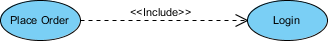
Use Case Example – Include Relationship
The include relationship adds additional functionality not specified in the base use case. The <<Include>> relationship is used to include common behavior from an included use case into a base use case in order to support the reuse of common behavior.
What is a <<Extend>> Use Case?
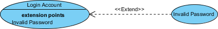
- Indicates that an “Invalid Password” use case may include (subject to specified in the extension) the behavior specified by base use case “Login Account”.
- Depict with a directed arrow having a dotted line. The tip of arrowhead points to the base use case and the child use case is connected at the base of the arrow.
- The stereotype “<<extends>>” identifies as an extend relationship
Extend Relationship
The extend relationships are important because they show optional functionality or system behavior. The <<extend>> relationship is used to include optional behavior from an extending use case in an extended use case. In the example above, there is an extend connector with an extension point “Invalid Password”.
Abstract and generalized Use Case
The general use case is abstract. It can not be instantiated, as it contains incomplete information. The title of an abstract use case is shown in italics.

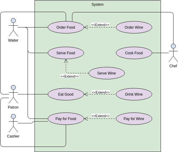
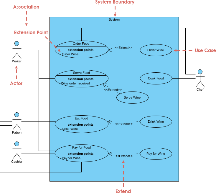
Use Case Diagram Example
This example of a use case diagram depicts a model of several business use cases (goals) that represent the interaction between a restaurant (business system) and its key stakeholders (business participants and business workers). Having identified the basic use cases in the first round of cuts, perhaps we can further build these use cases with “extend” and “include” use cases in the second round of revisions.
This post is also available in Deutsche, Español, فارسی, Français, English, Bahasa Indonesia, 日本語, Polski, Portuguese, Ру́сский, Việt Nam, 简体中文 and 繁體中文.
