


State Diagram – A Quick Tutorial
What is a UML state diagram?
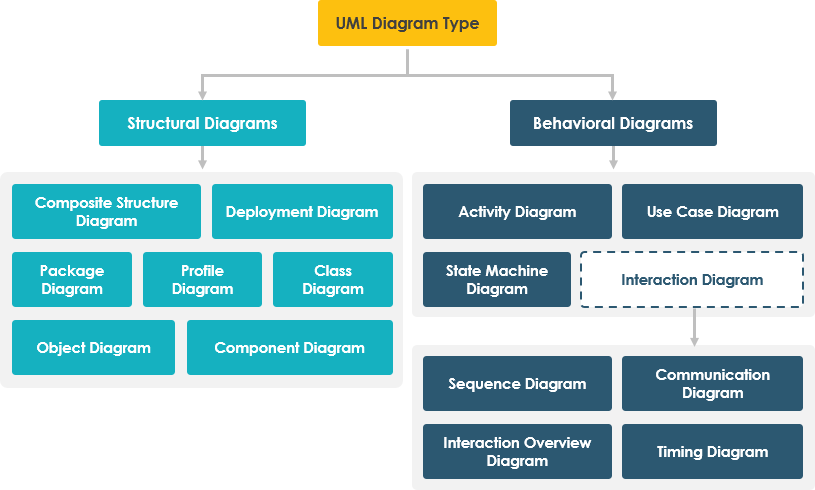
A state diagram (called in the UML 1.x specification) is a diagram showing a state machine and is called a state machine diagram in UML 2.x. The so-called state machine is a behavior that describes the various states and state transitions of an object in its life cycle. A state diagram is one of the 14 UML diagrams used for modeling in UML 2.0.
It defines the different states of an object during its lifecycle, which change in response to events. State diagrams are useful for modeling reactive systems, which can be defined as systems that react to external or internal events. A state diagram describes the flow of control from one state to another. A state is defined as a condition for the existence of an object that changes when an event is triggered.
What is the purpose of a state diagram?
The important purpose of a state diagram is to model the life cycle of an object from creation to termination.
- Model the dynamic aspects of the system and to provide a more comprehensive representation of the information about the system.
- Describe the different states of an object in its life cycle, whether it is in a triggered state, a dormant state, or a dead state.
- Model the life cycle of an object, which helps the programmer to design the methods of the object, etc.
- Help programmers to understand requirements and improve coding speed.
The Components of UML state diagram
UML state diagram is mainly composed of five elements, namely state, transition, event, action and activity.
Actually, state diagrams can be very complex – you can nest state diagrams, place guards (true / false) before states, add actions triggered by state changes, or even defer events to be processed later. These diagrams can take up a lot of text, and the conditions are usually written for a specific programming language. This can make diagrams look complex, but it can also make programming (and testing) faster since there is less potential for misinterpretation.
Edit this State Machine Diagram
Components of a UML State Diagram
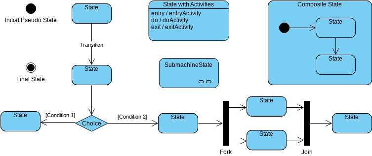
UML state diagrams use symbols that you may have seen in UML activity diagrams.
- Start state: solid circle.
- End state: solid circle with rounded corners.
- State: rectangle with rounded corners with the name of the action.
- Transition: Connected arrow with label indicating the trigger for that transition (if any).
- States with internal activity: States with horizontal lines whose behavior is listed in the lower half.
- Composite states: states with horizontal lines and nested state diagrams (or links to another draw.io page) in the lower half.
- Guards or conditions: Diamonds.
- Fork: A thicker line with one transition input and two or more outputs.
- Join: A thicker line with more than one transition input and only one transition.
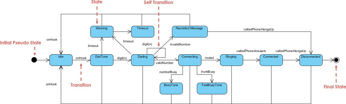
State Machine Diagram Example – Phone Call
In this example of a state diagram, the phone line is idle at the start of the call. When the phone is removed from the hook, it emits a dial tone and can accept digits for dialing. Once a valid number is entered, the phone system attempts to connect the call and route it to the appropriate destination. If the number or the trunk is busy, the connection may fail. If the connection is successful, the called phone starts ringing. When the line is hung up again, the phone line will return to idle.
Edit this State Machine Diagram
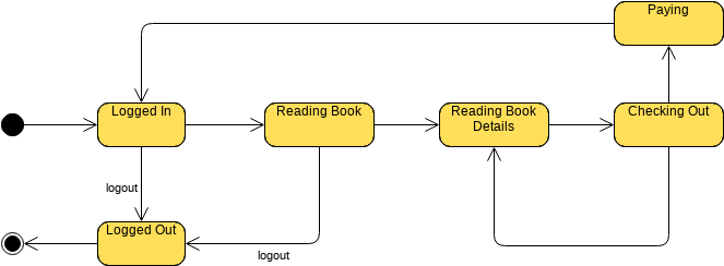
UML state diagram example – Online Bookshop

Edit this State Machine Diagram
This post is also available in Deutsche, Español, فارسی, Français, English, Bahasa Indonesia, 日本語, Polski, Portuguese, Ру́сский, Việt Nam, 简体中文 and 繁體中文.
