Step-by-Step Class Diagram Tutorial Using Visual Paradigm
What is a Class Diagram?
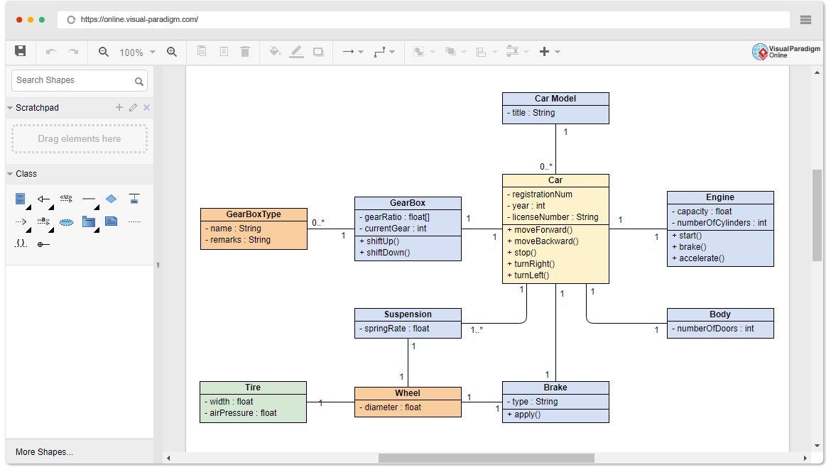
A class diagram is a static structure diagram in UML (Unified Modeling Language) that shows the system’s classes, their attributes, methods (operations), and the relationships between objects. It is used to model the static view of an application.
Why Use a Class Diagram?
- Visual Representation: Provides a clear visual representation of the system’s structure.
- Communication: Helps in communicating the design of the system to stakeholders.
- Blueprint: Acts as a blueprint for the system’s implementation.
- Documentation: Serves as documentation for the system’s design.
When to Use a Class Diagram?
- Design Phase: During the design phase of software development to model the system’s structure.
- Refactoring: When refactoring existing systems to understand and improve the system’s design.
- Documentation: For documenting the system’s architecture and design.
The Best Choice of UML Tool for Developers
When it comes to UML modeling, Visual Paradigm stands out as one of the best choices for developers. Here’s why:
- Comprehensive Toolset: Visual Paradigm offers a wide range of diagramming tools, including class diagrams, sequence diagrams, use case diagrams, and more. This comprehensive toolset ensures that you can model every aspect of your system with precision.
- User-Friendly Interface: With an intuitive and user-friendly interface, Visual Paradigm makes it easy for developers to create and manage complex diagrams. The drag-and-drop functionality and clear layout options streamline the design process.
- Advanced Features: Visual Paradigm includes advanced features such as code engineering, model-driven architecture (MDA), and agile development support. These features help developers transition seamlessly from design to implementation.
- Collaboration Tools: Visual Paradigm supports team collaboration with features like version control, teamwork client, and real-time collaboration. This makes it easier for teams to work together on large projects, ensuring consistency and accuracy.
- Integration Capabilities: Visual Paradigm integrates smoothly with popular development environments and tools, such as Eclipse, Visual Studio, and various version control systems. This integration enhances productivity and ensures a cohesive workflow.
- Extensive Documentation and Support: Visual Paradigm provides extensive documentation, tutorials, and customer support to help developers get the most out of the tool. Whether you’re a beginner or an experienced user, you’ll find the resources you need to succeed.
Visual Paradigm is not just a UML tool; it’s a comprehensive solution that empowers developers to create high-quality models, collaborate effectively, and streamline the development process. Choose Visual Paradigm for your UML needs and experience the difference it can make in your projects.
How to Create a Class Diagram Using Visual Paradigm
Step 1: Open Visual Paradigm
- Launch Visual Paradigm.
- Create a new project or open an existing one.
Step 2: Create a New Class Diagram
- In the Project Browser, right-click on the project name.
- Select
New Diagram>Class Diagram. - Name your diagram (e.g., “Academic System Class Diagram”) and click
OK.
Step 3: Add Classes
- From the Diagram Toolbar, select the
Classtool. - Click on the diagram canvas to add a new class.
- Name the class (e.g.,
Person).
Step 4: Define Attributes and Methods
- Double-click on the class to open the Specification window.
- In the
Attributestab, add the attributes (e.g.,name: str,phoneNumber: str,emailAddress: str). - In the
Operationstab, add the methods (e.g.,+purchaseParkingPass(): void).
Step 5: Add More Classes
- Repeat steps 3 and 4 to add more classes (e.g.,
Address,Student,Professor). - Define their attributes and methods as follows:
- Address Class:
- Attributes:
street: str,city: str,state: str,postalCode: int,country: str - Methods:
+validate(): bool,+outputAsLabel(): str
- Attributes:
- Student Class:
- Attributes:
studentNumber: int,averageMark: int - Methods:
+isEligibleToEnroll(str): bool,+getSeminarsTaken(): int
- Attributes:
- Professor Class:
- Attributes:
salary: int,staffNumber: int,yearsOfService: int,numberOfClasses: int
- Attributes:
- Address Class:
Step 6: Establish Relationships
- From the Diagram Toolbar, select the
Associationtool. - Click on the source class (e.g.,
Person) and drag to the target class (e.g.,Address). - Define the multiplicity (e.g., 0..1 to 1 for
Personlives atAddress).
Step 7: Define Inheritance
- From the Diagram Toolbar, select the
Generalizationtool. - Click on the subclass (e.g.,
Student) and drag to the superclass (e.g.,Person). - Repeat for
Professor.
Step 8: Add Multiplicity and Roles
- Double-click on the association line to open the Specification window.
- Define the multiplicity and roles (e.g., 0..* to 1..5 for
StudentsupervisesProfessor).
Step 9: Finalize the Diagram
- Arrange the classes and relationships for clarity.
- Save the diagram.
Step 10: Generate Documentation (Optional)
- Go to
Tools>Document>Document Composer. - Select the diagram and generate the documentation.
Example Diagram
Here is an example of what the final class diagram might look like:
Conclusion
Creating a class diagram is a fundamental step in the design phase of software development, providing a clear visual representation of the system’s structure. This tutorial has walked you through the process of creating a class diagram using Visual Paradigm, detailing the steps from opening the tool to finalizing the diagram.
We started by understanding what a class diagram is and why it is essential for modeling the static view of an application. We then explored when to use a class diagram, emphasizing its importance during the design phase, refactoring, and documentation.
The step-by-step guide covered the creation of classes, defining their attributes and methods, establishing relationships, and defining inheritance. We also discussed how to add multiplicity and roles to associations, ensuring a comprehensive and accurate representation of the system’s structure.
The example diagram provided a practical illustration of an academic system, including Person, Address, Student, and Professor classes, along with their relationships. This example demonstrated how to model real-world entities and their interactions within a system.
By following this tutorial, you should now be equipped with the knowledge and skills to create effective class diagrams using Visual Paradigm. These diagrams will serve as valuable blueprints for implementation, aiding in communication with stakeholders and ensuring a well-documented system design.
UML Diagram Examples
(Edit Instantly)
This post is also available in Deutsche, Español, فارسی, Français, Bahasa Indonesia, 日本語, Polski, Portuguese, Ру́сский, Việt Nam, 简体中文 and 繁體中文.


