


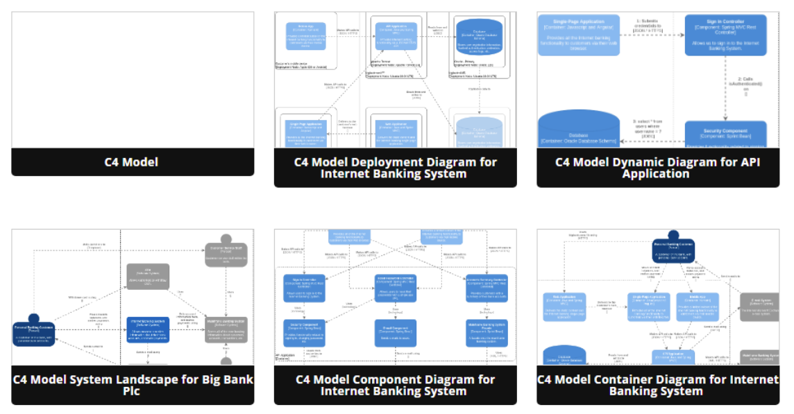
Introduction to C4 Model: a Quick Guide
Introduction
The C4 model, developed by Simon Brown, offers a structured approach to software architecture diagramming, consisting of four distinct levels that progressively zoom in on the architecture of a software system. Each level provides a unique perspective and serves specific purposes in documenting and communicating software architecture. Let’s explore the four levels of the C4 model:
1. System Context Diagram
Scope: A single software system.
Primary Elements: The software system in scope.
Supporting Elements: People (e.g., users, actors, roles, personas) and software systems (external dependencies) directly connected to the software system in scope.
Intended Audience: Everyone, both technical and non-technical individuals, inside and outside of the software development team.
Purpose: A System Context diagram offers an initial, high-level view of a software system’s architecture. It serves as the starting point for architectural documentation, providing a holistic perspective of the system within its broader environment. In this diagram, the software system is depicted as a central box, surrounded by its users and other external systems it interacts with. The focus is on people and software systems, not on technical details like technologies or protocols.
Recommended for Most Teams: Yes.
Key Characteristics:
- Offers a bird’s-eye view of the system.
- Emphasizes interactions between the system and its users/external systems.
- Ideal for communicating with non-technical stakeholders.
- Detail level is intentionally kept low.
2. Container Diagram
Scope: A single software system.
Primary Elements: Containers within the software system in scope (e.g., server-side web applications, single-page applications, databases, etc.).
Supporting Elements: People and software systems directly connected to the containers.
Intended Audience: Technical individuals inside and outside of the software development team, including software architects, developers, and operations/support staff.
Purpose: The Container diagram dives deeper into the software system, focusing on its high-level structure and the distribution of responsibilities across containers. Containers represent separately runnable or deployable units, such as web applications or databases. This diagram also highlights the major technology choices and illustrates how containers communicate with one another. It’s a valuable tool for both developers and support/operations staff.
Recommended for Most Teams: Yes.
Key Characteristics:
- Zooms in on the software system’s architecture.
- Depicts containers and their interactions.
- Highlights technology choices.
- Suitable for technical stakeholders.
- Does not address deployment-specific details like clustering or load balancing.
3. Component Diagram
Scope: A single container.
Primary Elements: Components within the container in scope.
Supporting Elements: Containers (within the software system in scope) and people and software systems directly connected to the components.
Intended Audience: Software architects and developers.
Purpose: The Component diagram offers a detailed view of a container’s internal structure. It breaks down the container into its major structural building blocks, known as components. These components are responsible for specific tasks within the container and are associated with technology and implementation details. This diagram is particularly useful for software architects and developers who need to understand the finer-grained aspects of the container’s architecture.
Recommended for Most Teams: No, only create component diagrams if they add value, and consider automating their creation for long-lived documentation.
Key Characteristics:
- Focuses on the internal structure of a container.
- Identifies components, their responsibilities, and implementation details.
- Targets technical stakeholders.
- Not always necessary and should be used judiciously when it adds value to the documentation.
4. Code Diagram
Scope: A single component.
Primary Elements: The detailed code and technical artifacts within a specific component.
Supporting Elements: Components (within the container in scope), containers (within the software system in scope), and people and software systems directly connected to the components.
Intended Audience: Highly technical individuals, typically developers and those deeply involved in the codebase.
Purpose: The final level of the C4 model, the Code diagram, zooms in even further to provide an in-depth view of a specific component’s codebase. This diagram delves into the actual source code, class structures, and technical implementation details within the component. It is particularly useful for developers who need to work on or understand the inner workings of a specific component.
Recommended for Most Teams: Rarely used in practice. It is generally not common to create Code diagrams, as the level of detail they provide is often covered within code documentation and development environments.
Key Characteristics:
- Focuses on the actual source code and technical artifacts.
- Provides an extremely detailed view of a component’s implementation.
- Primarily intended for developers working on the code.
- Rarely used in practice due to its high level of detail, as this information is typically available within the codebase itself.
Conclusion
The four levels of the C4 model provide a structured hierarchy for documenting and communicating software architecture, starting from a high-level overview in the System Context diagram and gradually drilling down to the actual code in the Code diagram. These diagrams cater to various audiences, from non-technical stakeholders who benefit from the big picture to highly technical developers who require in-depth code-level insights. By employing the C4 model, software architects and development teams can effectively convey complex architectural designs and foster better understanding and collaboration within and outside their organizations.
This post is also available in Deutsche, Español, فارسی, Français, English, Bahasa Indonesia, 日本語, Polski, Portuguese, Ру́сский, Việt Nam, 简体中文 and 繁體中文.
