


Bridging Vision and Execution: A Case Study in Mastering Use Case Descriptions
Introduction
In modern software engineering, misaligned requirements remain one of the leading causes of project delays, scope creep, and stakeholder dissatisfaction. While visual modeling techniques like Use Case Diagrams effectively illustrate system boundaries, actors, and high-level goals, they inherently lack the granular detail required for development, testing, and quality assurance. This is where Use Case Descriptions become indispensable.
A well-crafted use case narrative transforms abstract system goals into actionable, step-by-step specifications. By documenting precise interactions, decision points, and error-handling pathways, teams establish a single source of truth that aligns product owners, developers, testers, and business analysts. This case study explores the anatomy of effective use case documentation, demonstrating how structured narratives, standardized templates, and complementary visual models converge to produce unambiguous functional specifications. Through a practical ATM withdrawal scenario, we will examine how to capture business logic, manage deviations, and maintain traceability from concept to implementation.

1. Foundational Concepts
Before authoring detailed specifications, it is essential to understand the core components that give a use case its structural integrity:
-
Actor: Any entity (human, external system, or hardware) that interacts with the system to achieve a goal.
-
Primary Actor: Initiates the interaction to fulfill a specific objective (e.g., a Bank Customer).
-
Secondary/Supporting Actor: Provides necessary services or data to the system during execution (e.g., a Core Banking API or Payment Gateway).
-
-
Preconditions: The state of the system or environment that must already exist before the use case can begin. These are assumed true and are not validated within the flow.
-
Trigger: The specific event or user action that initiates the use case.
-
Main Success Scenario (Basic Flow): The optimal, error-free sequence of steps that leads to the successful completion of the actor’s goal. Often referred to as the “happy path.”
-
Extensions / Alternative & Exception Flows: Documented deviations from the main flow.
-
Alternative Flows: Different valid paths to achieve the same goal (e.g., using a different payment method).
-
Exception Flows: Error conditions, validation failures, or system constraints that interrupt the goal and require specific handling.
-
-
Postconditions: The guaranteed state of the system, data, or environment after successful completion of the use case.
2. The Standard Specification Template
Consistency is critical for maintainability. The following template provides a widely adopted structure that ensures completeness without unnecessary verbosity:
| Field | Description |
|---|---|
| Use Case ID & Name | A unique identifier and a verb-noun title (e.g., UC-201: Withdraw Cash). |
| Actor(s) | Lists all primary and secondary participants. |
| Description | A concise summary of the use case’s purpose and business value. |
| Preconditions | System or environmental states required before initiation. |
| Trigger | The exact event that starts the interaction. |
| Main Success Scenario | Numbered, sequential steps detailing the default successful path. |
| Extensions / Exceptions | Branching flows mapped to specific main scenario steps (e.g., 3a, 8b). |
| Postconditions | The final system state upon successful completion. |
3. Case Study Narrative: UC-201 Withdraw Cash
The following specification demonstrates how the template and foundational concepts are applied to a real-world banking scenario.
Use Case ID & Name: UC-201 - Withdraw Cash
Primary Actor: Bank Customer
Secondary Actor: Core Banking System / ATM Network
Description: Describes how an authenticated bank customer withdraws cash from their checking or savings account using an automated teller machine (ATM).
Preconditions: The ATM maintains an active network connection and contains sufficient physical currency.
Trigger: The Customer inserts their bank card into the ATM card reader.
Main Success Scenario (Basic Flow)
-
System reads the bank card and prompts for a Personal Identification Number (PIN).
-
Customer enters their PIN.
-
System validates the PIN with the Core Banking System.
-
System displays available transaction options.
-
Customer selects “Withdraw Cash”.
-
System prompts for account type (Checking/Savings) and withdrawal amount.
-
Customer selects the target account and enters an available amount.
-
System verifies sufficient funds with the Core Banking System.
-
System debits the account and commands the cash dispenser to release the specified amount.
-
System dispenses cash, ejects the card, and prints a transaction receipt.
-
Customer collects cash, card, and receipt.
Extensions (Alternative & Exception Flows)
-
3a. Invalid PIN:
-
System notifies the Customer of the incorrect PIN and requests re-entry.
-
Customer enters a new PIN.
-
Resume at step 3.
-
Exception: If the customer enters an invalid PIN three consecutive times, the system retains the card and terminates the session.
-
-
8a. Insufficient Funds:
-
System displays an “Insufficient Funds” error and prompts the Customer to enter a lower amount or cancel.
-
Customer selects “Cancel”.
-
System ejects the card and terminates the session.
-
Postconditions
The transaction is securely logged, the account balance is accurately updated, the physical ATM currency inventory is reduced accordingly, and the terminal resets to the idle welcome screen.
4. Authoring Best Practices
To ensure use case descriptions remain actionable, scalable, and developer-friendly, adhere to these established guidelines:
-
Maintain a Black-Box Perspective: Document what the system does from the user’s viewpoint, not how it achieves it internally. Avoid referencing database schemas, API endpoints, or UI pixel placements.
-
Employ Active Voice & Clear Syntax: Use direct subject-verb constructions to eliminate ambiguity.
-
Avoid: “The PIN is evaluated by the system.”
-
Preferred: “The System validates the PIN.”
-
-
Map Extensions Explicitly: Always tie alternative and exception flows directly to the step number they diverge from (e.g.,
5abranches from step 5). This preserves traceability and simplifies test case generation. -
Target Elementary Business Processes (EBP): Each use case should represent a complete, valuable task performed by one actor in response to a single business event. Avoid documenting granular UI clicks or system micro-interactions.
-
Separate Preconditions from Triggers: A precondition is a static state (e.g., “User has an active session”), while a trigger is a dynamic action (e.g., “User clicks ‘Submit Order'”). Keeping them distinct prevents logical overlap and scope confusion.
5. Visualizing System Interactions
While textual narratives provide depth, visual models offer immediate structural clarity. Integrating Use Case Diagrams and Sequence Diagrams alongside specifications ensures stakeholders share a unified understanding of system boundaries and temporal execution.
A. Use Case Relationship Diagram
This diagram maps actor interactions, defines system boundaries, and illustrates inclusion relationships between reusable behaviors.
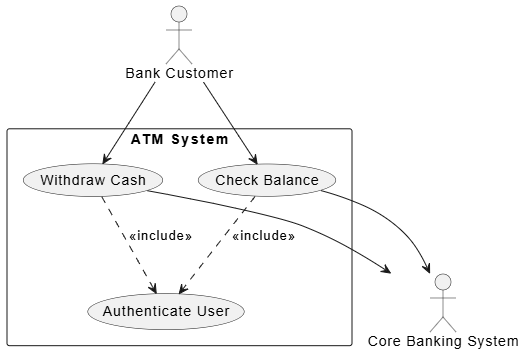
@startuml
skinparam theme plain
skinparam packageStyle rectangle

actor "Bank Customer" as customer
actor "Core Banking System" as bank

rectangle "ATM System" {
    usecase "Withdraw Cash" as UC_Withdraw
    usecase "Check Balance" as UC_Balance
    usecase "Authenticate User" as UC_Auth

    ' Inclusion relationship
    UC_Withdraw ..> UC_Auth : <<include>>
    UC_Balance ..> UC_Auth : <<include>>
}

customer --> UC_Withdraw
customer --> UC_Balance
UC_Withdraw --> bank
UC_Balance --> bank
@endum
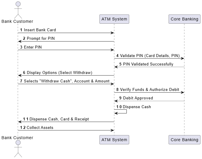
B. Sequence Diagram for the Main Success Scenario
This diagram translates the Main Success Scenario (withdraw cash use case) into a chronological timeline, clarifying message flow, synchronization points, and system-to-system handoffs.
@startuml
skinparam theme plain
autonumber

actor "Bank Customer" as Customer
participant "ATM System" as ATM
participant "Core Banking" as Bank

Customer -> ATM : Insert Bank Card
ATM -> Customer : Prompt for PIN
Customer -> ATM : Enter PIN
ATM -> Bank : Validate PIN (Card Details, PIN)
Bank --> ATM : PIN Validated Successfully

ATM -> Customer : Display Options (Select Withdraw)
Customer -> ATM : Selects "Withdraw Cash", Account & Amount
ATM -> Bank : Verify Funds & Authorize Debit
Bank --> ATM : Debit Approved

ATM -> ATM : Dispense Cash
ATM -> Customer : Dispense Cash, Card & Receipt
Customer -> ATM : Collect Assets
@enduml
Conclusion
Use case descriptions are far more than documentation artifacts; they are foundational contracts that align business intent with technical execution. By combining a disciplined narrative structure, explicit branching logic, and complementary visual models, engineering teams can eliminate ambiguity, streamline test automation, and reduce costly rework. The case study presented here demonstrates that clarity emerges not from complexity, but from consistency, precision, and a relentless focus on the actor’s goal. As systems grow increasingly distributed and AI-augmented, the principles of structured use case modeling will remain indispensable for translating human requirements into reliable, scalable software.
This post is also available in Deutsche, Español, فارسی, Français, English, Bahasa Indonesia, 日本語, Polski, Portuguese, Ру́сский, Việt Nam, 简体中文 and 繁體中文.
