


Bridging Requirements and Design: A Practical Guide to Use Case Modeling with UML and PlantUML
Introduction
In modern software engineering, the gap between stakeholder expectations and technical implementation remains one of the most frequent sources of project friction. Requirements documents written in natural language are often verbose, ambiguous, and open to interpretation. Use Case modeling emerged as a standardized solution to this problem, offering a visual, outside-in perspective that captures exactly what a system must do, who interacts with it, and where the system’s boundaries lie.
This case study explores how to translate fragmented functional requirements into precise, testable architectural blueprints using UML 2.0 Use Case diagrams. By walking through a real-world-inspired scenario, we will examine core modeling concepts, demonstrate practical implementation using PlantUML, and establish a repeatable framework for capturing requirements with clarity, consistency, and developer-ready precision.

Case Study Context: The Enterprise Content Platform
A mid-sized technology firm was tasked with building a modular Content Management System (CMS) designed to serve multiple content verticals, support role-based access control, and integrate with third-party credential verification services. The initial requirements phase produced over 80 pages of overlapping feature descriptions, compliance mandates, and integration notes.
To streamline development, testing, and stakeholder alignment, the architecture team adopted a Use Case modeling approach. The goal was to isolate functional boundaries, identify all interacting entities (human and system), and establish explicit pass/fail criteria for every user journey before writing a single line of code.
Core Modeling Concepts
Before diving into diagrams, the team established a shared vocabulary to ensure consistent interpretation:
-
Actors: External entities that initiate interactions or receive outputs from the system. Actors are not limited to human users; they encompass secondary stakeholders such as auditors, maintainers, external APIs, or legacy databases.
-
Use Cases: Discrete, goal-oriented interactions represented as ovals. Each use case captures a complete unit of work that delivers tangible value to an actor.
-
System Boundary: A rectangular container that explicitly separates internal system functionality from external actors and dependencies.
-
Relationships:
-
Association: A solid line linking an actor to a use case, indicating direct interaction.
-
Actor Generalization: A solid arrow with a hollow triangle denoting inheritance. A specialized actor inherits all capabilities of a base actor while adding exclusive functions.
-
«include»: A dotted arrow indicating mandatory reuse. The base use case explicitly and completely executes the steps of the included use case every time. -
«extend»: A dotted arrow indicating optional, conditional behavior. The extending use case only triggers under specific runtime conditions or exception paths.
-
Visual Implementation with PlantUML
To maintain version control, enable collaborative editing, and generate diagrams programmatically, the team adopted PlantUML. Below are the architectural models developed during the CMS requirement refinement phase.
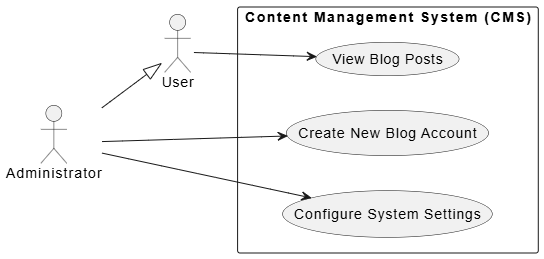
Example A: Core Mechanics & Actor Generalization
This diagram establishes the foundational system boundary, primary user roles, and inheritance hierarchies. It clarifies that an Administrator possesses all standard User capabilities while retaining exclusive system-level functions.
@startuml
left to right direction
skinparam packageStyle rectangle

actor "User" as user
actor "Administrator" as admin

' Actor Generalization (Inheritance)
admin --|> user

rectangle "Content Management System (CMS)" {
    usecase "View Blog Posts" as UC1
    usecase "Create New Blog Account" as UC2
    usecase "Configure System Settings" as UC3
}

user --> UC1
admin --> UC2
admin --> UC3
@enduml
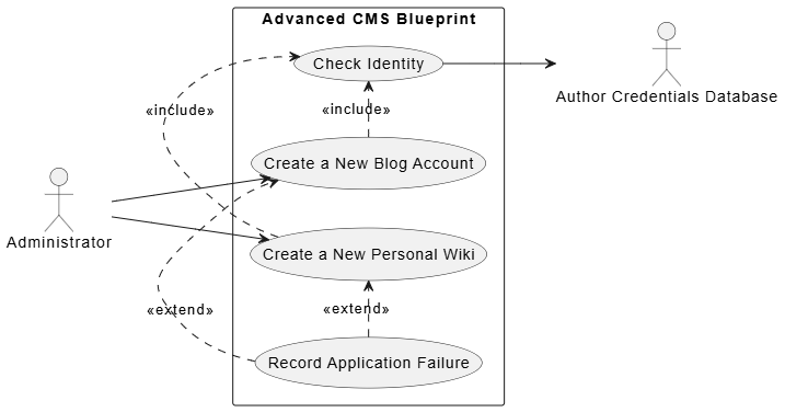
Example B: Advanced Relationships («include» and «extend»)
As the team mapped complex workflows, they identified recurring validation steps and conditional failure paths. This diagram demonstrates how to factor out mandatory checks using «include» and how to handle optional exception flows using «extend».
@startuml
left to right direction

actor "Administrator" as admin
actor "Author Credentials Database" as db

rectangle "Advanced CMS Blueprint" {
    usecase "Create a New Blog Account" as blog
    usecase "Create a New Personal Wiki" as wiki
    usecase "Check Identity" as check
    usecase "Record Application Failure" as failure
}

admin --> blog
admin --> wiki

' Include Relationship: Both parent use cases fully reuse Check Identity
blog .> check : <<include>>
wiki .> check : <<include>>

' Check Identity maps directly to the external validation system
check --> db

' Extend Relationship: Optional flow triggered on application failure
failure .> blog : <<extend>>
failure .> wiki : <<extend>>
@enduml
Modeling Guidelines & Best Practices
Throughout the CMS project, the architecture team codified a set of non-negotiable rules to ensure diagram accuracy and downstream usability:
-
Maintain Strict Synchronization: Diagrams must remain in perfect alignment with textual use case specifications. If a narrative step references an external API, database, or compliance module, that entity must be explicitly modeled as an actor on the diagram.
-
Capture “What,” Not “How”: Use cases are strictly functional. Non-functional constraints (performance targets, UI frameworks, deployment pipelines, or programming languages) belong in supplementary requirement documents, not in the use case model.
-
Enforce Boundary Discipline: All actors reside outside the system boundary rectangle. Only functional ovals representing internal system capabilities belong inside. This prevents architectural confusion during handoff.
-
Define Deterministic Pass/Fail Criteria: Every use case must map to verifiable acceptance criteria. Product owners, developers, and QA engineers must be able to independently agree on whether a use case executed successfully or failed.
Expert Tips & Field Insights
After multiple iteration cycles, the team documented several recurring pitfalls and actionable strategies for future projects:
-
Never Leave Diagrams Naked: A standalone diagram of actors and ovals is merely a structural sketch. Every use case must be paired with a textual specification detailing preconditions, primary success paths, alternative flows, and postconditions. Without this context, developers lack actionable implementation criteria.
-
Do Not Confuse
«extend»with Inheritance: Object-oriented programmers frequently mistake the«extend»stereotype for class inheritance. In UML, inheritance uses a solid line with a hollow triangle. The dotted«extend»arrow strictly denotes an optional, conditional runtime variant, not a structural hierarchy. -
Beware of the Actor Blindspot: Focusing solely on primary end-users leads to architectural gaps. Proactively identify secondary actors: compliance auditors, system installers, automated migration scripts, logging services, or third-party gateways. Omitting these stakeholders often surfaces catastrophic integration constraints late in development.
-
Embrace Iterative Refinement: Initial diagrams are hypotheses, not final artifacts. As textual descriptions are drafted, missing actors will surface, redundant steps will emerge, and complex flows will naturally factor into
«include»packages. Treat diagrams as living documents that evolve alongside requirement discovery.
Conclusion
Use Case modeling remains one of the most effective techniques for translating ambiguous stakeholder needs into precise, testable system architectures. By clearly delineating system boundaries, mapping actor relationships, and strategically applying «include» and «extend» semantics, teams can eliminate requirement ambiguity before development begins.
The integration of textual specifications with PlantUML-generated diagrams creates a transparent, version-controlled requirement artifact that serves product managers, developers, and QA engineers equally well. As demonstrated in this case study, the true power of use case modeling lies not in the diagrams themselves, but in the disciplined, iterative process of defining exactly what the system must do, who depends on it, and how success is measured. When applied consistently, this approach dramatically reduces rework, accelerates onboarding, and ensures that every line of code traces directly back to a validated user requirement.
This post is also available in Deutsche, Español, فارسی, Français, English, Bahasa Indonesia, 日本語, Polski, Portuguese, Ру́сский, Việt Nam, 简体中文 and 繁體中文.
