


Structuring System Behavior: A Practical Guide to UML Use Case Relationships
Introduction
In modern software engineering, use case diagrams are frequently misunderstood as mere feature inventories or high-level project roadmaps. In reality, they serve as architectural scaffolding. When applied correctly, use case relationships do not simply list what a system should do; they actively decompose complex behaviors into manageable, reusable, and logically coherent modules. This structural clarity bridges the gap between stakeholder expectations and development execution, ensuring that detailed design documentation remains maintainable, unambiguous, and aligned with actual runtime behavior.
This case study explores how to leverage the three core UML 2.0 use case relationships—<<include>>, Generalization, and <<extend>>—to architect a scalable enterprise platform. Through practical examples, textual documentation mappings, and industry-proven guidelines, we will demonstrate how these relationships transform sprawling requirement documents into streamlined, developer-ready blueprints.

Case Study Context: The Horizon Platform
To ground these concepts in reality, we will examine the architectural design of the Horizon Platform, an enterprise-grade system responsible for managing user accounts, content creation workflows, and external identity verification. As requirements scaled, the engineering team faced two critical challenges:
-
Documentation bloat: Repetitive validation and error-handling steps were copy-pasted across dozens of functional specifications.
-
Ambiguous variations: Specialized account types and conditional failure paths were muddled together, causing scope creep and inconsistent implementation.
By applying UML use case relationships strategically, the team resolved both issues. The following sections detail how each relationship was applied, visualized, and documented.
1. The <<include>> Relationship: Enforcing Behavioral Reuse
Purpose & Mechanism
The <<include>> relationship exists to eliminate redundancy. When multiple use cases share identical procedural steps, those steps are extracted into a standalone sub-use case. The base use case explicitly incorporates this shared behavior, ensuring that the included steps are always executed as part of the primary flow.
Crucially, the included use case does not require a direct actor association. It automatically inherits the contextual connection from whichever base use case invokes it, keeping the diagram clean and focused on business goals rather than implementation minutiae.
PlantUML Visualization
In PlantUML, a dashed dependency arrow points from the base use case to the included use case.
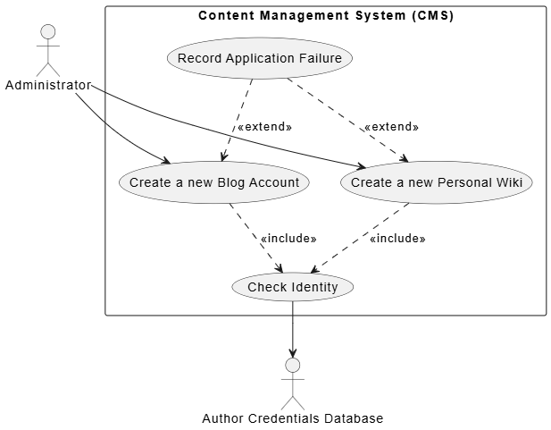
@startuml
skinparam theme plain
skinparam packageStyle rectangle

actor Administrator as admin
actor :Author Credentials Database: as db

rectangle "Content Management System (CMS)" {
    ' Include Example
    usecase "Create a new Blog Account" as UC_Blog
    usecase "Create a new Personal Wiki" as UC_Wiki
    usecase "Check Identity" as UC_Check

    UC_Blog ..> UC_Check : <<include>>
    UC_Wiki ..> UC_Check : <<include>>

    ' Extend Example
    usecase "Record Application Failure" as UC_Fail

    UC_Fail ..> UC_Blog : <<extend>>
    UC_Fail ..> UC_Wiki : <<extend>>
}

admin --> UC_Blog
admin --> UC_Wiki
UC_Check --> db
@enduml
Textual Documentation Mapping
Instead of rewriting identity validation steps across multiple specifications, the team adopted a standardized inclusion syntax in the main success flow:
| Use Case Field | Value / Flow Steps |
|---|---|
| Use Case Name | Create a new Blog Account |
| Main Success Flow | 1. Administrator selects account type.
2. Administrator enters author’s details. 3. include::Check Identity to verify author. 4. System creates the new blog account. |
2. Use Case Generalization (Inheritance): Managing Specialized Variations
Purpose & Mechanism
Generalization is applied when a base use case defines a core workflow that applies to multiple specialized contexts, each requiring only minor deviations. A child use case inherits all behaviors, goals, and relationships of its parent. Only the unique or overridden steps need to be documented in the child.
The “All-or-Nothing” Rule: Inheritance in use cases is strict. Every step defined in the parent must logically execute in the child. If a specialized scenario requires skipping or fundamentally altering a parent step, generalization is the wrong tool.
PlantUML Visualization
Generalization uses a solid line with a hollow arrowhead, pointing from the child to the parent.
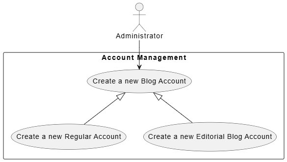
@startuml
skinparam theme plain
skinparam packageStyle rectangle

actor Administrator as admin

rectangle "Account Management" {
    usecase "Create a new Blog Account" as UC_Parent
    usecase "Create a new Regular Account" as UC_Regular
    usecase "Create a new Editorial Blog Account" as UC_Editorial

    ' Generalization arrows pointing to Parent
    UC_Parent <|-- UC_Regular
    UC_Parent <|-- UC_Editorial
}

admin --> UC_Parent
@enduml
3. The <<extend>> Relationship: Capturing Conditional & Optional Flows
Purpose & Mechanism
Unlike <<include>>, which represents mandatory reuse, <<extend>> models optional or conditional behavior that only triggers under specific runtime circumstances. The base use case remains fully functional on its own; the extending use case acts as a runtime “hook” that injects additional steps when predefined conditions are met.
Architecturally, this separates core success paths from exception handling, alternative routing, or optional add-ons, preventing bloated primary flows.
Textual Documentation Mapping
Extensions are typically mapped directly out of the alternative or exception flows in the textual specification:
| Use Case Field | Value / Flow Steps |
|---|---|
| Use Case Name | Create a new Blog Account |
| Failed End Condition | The application for a new blog account is rejected. |
| Extensions Section | Step 3.1: Author Credentials Database does not verify details.
Step 3.2: extended by::Record Application Failure. |
4. Architectural Guidelines & Best Practices
Successfully applying these relationships requires discipline. The following guidelines emerged from iterative refinement during the Horizon Platform rollout:
-
Avoid Over-Modeling (“Arrow Soup”): Use case relationships are designed to combat documentation redundancy, not to micromanage UI interactions. If a step doesn’t represent a standalone sub-goal with clear pass/fail business criteria, keep it inline as text. Clicking a button or navigating a menu rarely warrants a dedicated use case.
-
The “Programmer’s Trap” with
<<extend>>: Developers with object-oriented backgrounds often mistakenly equate<<extend>>with class inheritance. It does not. Use case inheritance is exclusively handled by the generalization relationship. Treat<<extend>>strictly as an optional runtime plugin or conditional hook. -
Double-Check Generalization Dependencies: Before drawing a generalization arrow, rigorously verify that the child use case genuinely requires every single step of the parent. If a child needs to bypass, skip, or fundamentally alter parent steps, replace generalization with
<<include>>or<<extend>>. -
Isolate External Actors on Reusable Modules: When extracting a shared routine into an included use case (e.g.,
Check Identity), migrate the external supporting subsystem connection (e.g.,Author Credentials Database) directly to that sub-use case. This instantly clarifies dependency boundaries and keeps higher-level diagrams focused on business interactions rather than infrastructure details.
Conclusion
UML use case relationships are far more than diagramming conventions; they are structural design decisions that directly impact system maintainability, documentation clarity, and development velocity. By strategically applying <<include>> for mandatory reuse, Generalization for specialized variations, and <<extend>> for conditional flows, architects can transform sprawling requirement sets into modular, logically sound blueprints.
The true value of these relationships lies in their consistency across visual diagrams and textual specifications. When diagrams and functional narratives align, teams eliminate ambiguity, reduce redundant documentation, and establish a single source of truth that scales alongside the system. As platforms grow in complexity, mastering these relationships remains one of the most effective ways to ensure that architectural intent translates seamlessly into working software.
This post is also available in Deutsche, Español, فارسی, Français, English, Bahasa Indonesia, 日本語, Polski, Portuguese, Ру́сский, Việt Nam, 简体中文 and 繁體中文.
