


Architecting Systems with UML: A Comprehensive Case Study in Modern Engineering
Introduction
In contemporary software engineering, the gap between abstract business requirements and deployable, scalable code is often bridged by a single, standardized notation: the Unified Modeling Language (UML). As systems grow in complexity, distributed architecture, and cross-functional dependency, relying on informal sketches or isolated codebases introduces unacceptable risk. UML resolves this by providing a semantically rigorous, graphical language that transcends programming paradigms and development methodologies.
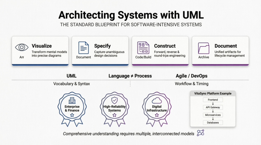
This case study examines how a modern engineering team applied UML across the full development lifecycle of an enterprise-grade system, demonstrating how visualization, specification, construction, and documentation converge to produce resilient, maintainable software-intensive architectures.
Case Study: Designing the “VitaSync” Distributed Care Platform
Project Context: VitaSync is a cloud-native, HIPAA-compliant telehealth and patient routing platform designed to handle high-reliability scheduling, real-time provider matching, and secure financial reconciliation. The engineering team adopted UML not as a rigid gatekeeping tool, but as a living blueprint that evolved alongside Agile delivery cycles.
1. Visualizing & Specifying: Translating Ambiguity into Structure
Before writing a single line of code, the architecture team needed to align clinical workflows, data compliance requirements, and microservice boundaries. UML provided the precise semantics required to eliminate interpretation gaps between product managers, backend engineers, and compliance auditors.
Applied Practice:
-
Visualizing: Mental models of patient routing logic were converted into standardized interaction diagrams, making distributed state transitions explicit.
-
Specifying: Unambiguous structural relationships were defined, ensuring that data ownership, API contracts, and security boundaries were formally captured.
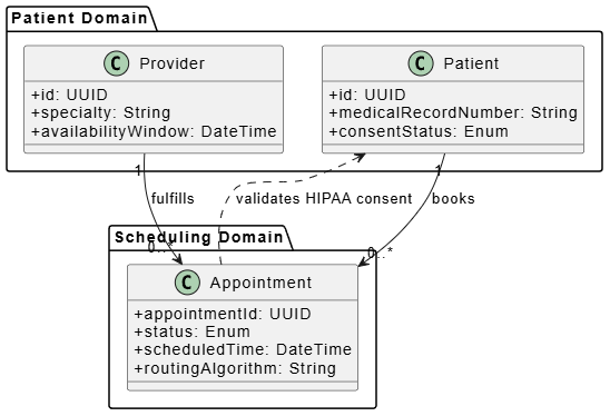
PlantUML Example 1: Class Diagram (Structural Specification)
@startuml
skinparam classAttributeIconSize 0
package "Patient Domain" {
  class Patient {
    +id: UUID
    +medicalRecordNumber: String
    +consentStatus: Enum
  }
  class Provider {
    +id: UUID
    +specialty: String
    +availabilityWindow: DateTime
  }
}

package "Scheduling Domain" {
  class Appointment {
    +appointmentId: UUID
    +status: Enum
    +scheduledTime: DateTime
    +routingAlgorithm: String
  }
}

Patient "1" --> "0..*" Appointment : books
Provider "1" --> "0..*" Appointment : fulfills
Appointment ..> Patient : validates HIPAA consent
@enduml
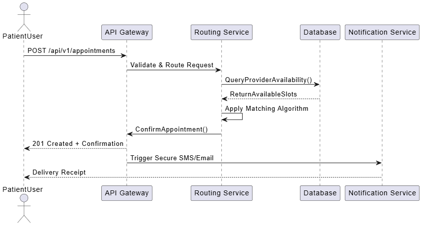
PlantUML Example 2: Sequence Diagram (Behavioral Visualization)
@startuml
actor PatientUser
participant "API Gateway" as GW
participant "Routing Service" as RS
participant "Database" as DB
participant "Notification Service" as NS

PatientUser -> GW: POST /api/v1/appointments
GW -> RS: Validate & Route Request
RS -> DB: QueryProviderAvailability()
DB --> RS: ReturnAvailableSlots
RS -> RS: Apply Matching Algorithm
RS -> GW: ConfirmAppointment()
GW --> PatientUser: 201 Created + Confirmation
GW -> NS: Trigger Secure SMS/Email
NS --> PatientUser: Delivery Receipt
@enduml
2. Constructing: Bridging Models and Code
UML models in this project were treated as engineering artifacts, not documentation afterthoughts. The team leveraged modern IDE integrations to enable forward and round-trip engineering, drastically reducing boilerplate and architectural drift.
Applied Practice:
-
Forward Engineering: UML class and deployment diagrams generated typed API stubs, DTOs, and Kubernetes manifest templates.
-
Round-Trip Engineering: When engineers refactored service boundaries in code, the UML diagrams were automatically synchronized, preserving architectural truth without manual diagram maintenance.
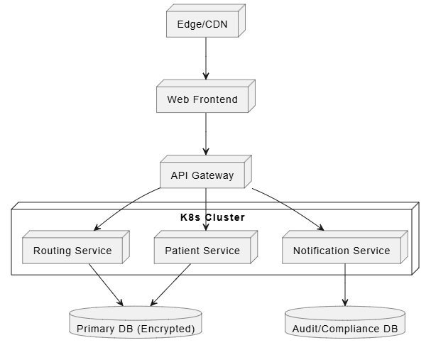
PlantUML Example 3: Deployment Diagram (Infrastructure Construction)
@startuml
node "Edge/CDN" as CDN
node "Web Frontend" as FE
node "API Gateway" as GW
node "K8s Cluster" as K8S {
  node "Patient Service" as PS
  node "Routing Service" as RS
  node "Notification Service" as NS
}
database "Primary DB (Encrypted)" as DB1
database "Audit/Compliance DB" as DB2

CDN --> FE
FE --> GW
GW --> PS
GW --> RS
GW --> NS
PS --> DB1
RS --> DB1
NS --> DB2
@enduml
3. Documenting: Capturing Lifecycle Artifacts
Beyond code generation, UML served as the canonical source of truth for audit trails, test planning, and release roadmaps. Every model was version-controlled alongside source code, ensuring that architectural decisions remained traceable through compliance reviews and post-incident retrospectives.
Applied Practice:
-
Documenting: Activity diagrams mapped approval workflows for clinical data access. State machine diagrams tracked appointment lifecycle transitions. All artifacts were linked to Jira epics and CI/CD pipeline gates.
PlantUML Example 4: Activity Diagram (Process Documentation)
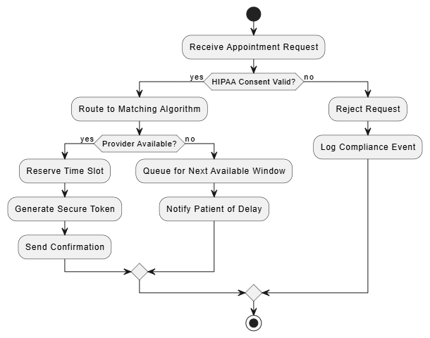
@startuml
start
:Receive Appointment Request;
if (HIPAA Consent Valid?) then (yes)
  :Route to Matching Algorithm;
  if (Provider Available?) then (yes)
    :Reserve Time Slot;
    :Generate Secure Token;
    :Send Confirmation;
  else (no)
    :Queue for Next Available Window;
    :Notify Patient of Delay;
  endif
else (no)
  :Reject Request;
  :Log Compliance Event;
endif
stop
@enduml
Models vs. Processes: Operationalizing the Language
A critical success factor in the VitaSync project was the explicit separation of UML (the language) from the delivery methodology (the process). The engineering team recognized that UML does not dictate when or how work should be organized; it only defines how to represent system artifacts accurately.
| UML (Language) | Software Process (Agile/DevOps) |
|---|---|
| Defines syntax for class relationships, interaction flows, and deployment nodes | Defines sprint cadence, backlog grooming, and CI/CD automation |
| Ensures diagrams are semantically unambiguous and tool-interpretable | Determines when models are created, reviewed, and retired |
| Enables round-trip synchronization between design and code | Governs team roles, testing strategies, and release validation |
By decoupling notation from methodology, the team could embed UML artifacts directly into their Agile workflow. Models were treated as “living documentation,” updated during refinement sessions and validated during code reviews, rather than being produced as static deliverables at phase gates.
Cross-Domain Application & Adaptability
While VitaSync is a software-intensive system, the modeling approach demonstrated UML’s adaptability to broader engineering contexts:
-
High-Reliability Infrastructure: Deployment and state diagrams were used to model failover logic and disaster recovery routing for telehealth endpoints.
-
Business & Compliance Workflows: Activity and use case models mapped patient consent flows, audit trails, and billing reconciliation, enabling legal and clinical stakeholders to validate system behavior without reading code.
-
Physical & Digital Convergence: Component diagrams bridged software services with hardware telemetry (e.g., remote monitoring devices), proving UML’s utility beyond pure codebases.
This versatility aligns with the core UML principle: comprehensive understanding requires multiple, interconnected views. No single diagram captured the entire system; instead, structural, behavioral, and deployment models formed a cohesive, cross-referenced architecture map.
Conclusion
The Unified Modeling Language remains an indispensable engineering asset because it transforms abstract complexity into actionable, unambiguous structure. As demonstrated in the VitaSync case study, UML’s true power lies not in rigid documentation, but in its ability to visualize intent, specify constraints, construct executable foundations, and document lifecycle artifacts in a single, standardized vocabulary.
When paired with modern development processes and automated tooling, UML bridges the gap between conceptual design and production-ready systems. It empowers cross-functional teams to align on architecture, accelerates code generation and synchronization, and ensures that critical knowledge survives personnel turnover and system evolution. In an era of distributed microservices, AI-augmented development, and stringent compliance requirements, UML continues to prove that a well-modeled system is a resilient system. By embracing its four foundational pillars and respecting the boundary between language and process, engineering organizations can navigate complexity with clarity, precision, and confidence.
This post is also available in Deutsche, Español, فارسی, Français, English, Bahasa Indonesia, 日本語, Polski, Portuguese, Ру́сский, Việt Nam, 简体中文 and 繁體中文.
