


Building Maintainable Systems: A Hands-On Guide to OOA/D
Introduction
In modern software engineering, the distance between a business problem and its technical implementation is often the primary source of project failure, scope creep, and unmaintainable code. Object-Oriented Analysis and Design (OOA/D) emerged as a disciplined methodology to bridge this divide, translating complex real-world processes into structured, modular, and scalable software architectures. Rather than jumping straight into coding, OOA/D mandates a systematic progression from understanding user intent to modeling conceptual domains, mapping dynamic interactions, and finally drafting static blueprints.
This case study explores the complete OOA/D lifecycle through a tangible, real-world scenario: an Automated Coffee Maker System. By walking through each phase of development, we will demonstrate how abstract principles manifest in practical design artifacts, ensuring that every line of future code remains tightly aligned with the original business requirements.

The Core Challenge: Bridging the “Representational Gap”
The foundational strength of OOA/D lies in its capacity to minimize the representational gap—the cognitive distance between how a real-world domain operates and how software objects solve domain problems.
-
Analysis (OOA) focuses on the real-world context, identifying what entities, concepts, and relationships exist.
-
Design (OOD) transitions into the software realm, determining how digital objects will communicate, manage state, and execute logic.
When software class names, structures, and interactions closely mirror our real-world mental models, the resulting system becomes inherently more readable, easier to debug, and significantly more adaptable to future changes. The following case study illustrates this transition step-by-step.
Phase 1: Requirements Analysis (Defining Use Cases)
Before architecting a single class or drawing a diagram, developers must clearly understand the user’s objectives. Use cases serve as narrative-driven requirement documents. They are not inherently object-oriented; rather, they are structured stories outlining how an external actor interacts with a system to achieve a measurable outcome.
Case Study Scenario: Brew a Coffee
Actor: Customer
Main Success Scenario:
-
Customer selects a beverage type (e.g., Espresso).
-
System verifies the availability of necessary water and coffee beans.
-
System deducts the appropriate ingredients, dispenses the beverage, and displays a completion message.
Alternative/Exception Scenario:
If ingredient levels fall below the required threshold, the system triggers a “Refill Required” alert and safely aborts the brewing sequence.
Phase 2: Object-Oriented Analysis (The Domain Model)
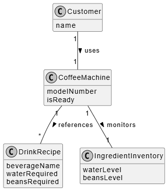
With requirements established, the next step is constructing a Domain Model. This is a visual snapshot of conceptual classes, their inherent attributes, and their real-world relationships.
Key Principle: A domain model exclusively represents real-world concepts. It deliberately avoids software implementation details, programming methods, or technical constraints.
Domain Model for the Coffee Maker
In this domain, the core conceptual entities include the Customer, CoffeeMachine, DrinkRecipe, and IngredientInventory. Their relationships dictate how the physical system behaves before a single line of code is written.
@startuml
skinparam handwritten false
skinparam monochrome true
hide methods

class Customer {
  name
}

class CoffeeMachine {
  modelNumber
  isReady
}

class DrinkRecipe {
  beverageName
  waterRequired
  beansRequired
}

class IngredientInventory {
  waterLevel
  beansLevel
}

Customer "1" -- "1" CoffeeMachine : uses >
CoffeeMachine "1" -- "1" IngredientInventory : monitors >
CoffeeMachine "1" -- "*" DrinkRecipe : references >
@endum
Phase 3: Object-Oriented Design (Interaction & Sequence Diagrams)
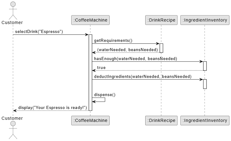
Transitioning from analysis to design, we shift from conceptual models to software objects. Responsibilities are assigned to specific classes, and message-passing protocols are defined. A Sequence Diagram provides a dynamic, time-ordered view of these software interactions.
Software objects do not simulate reality; they emulate it efficiently. Just as a real coffee machine orchestrates brewing internally, a CoffeeMachine software object will coordinate its own sub-processes by delegating messages to recipe and inventory components.
@startuml
skinparam monochrome true

actor Customer
participant ":CoffeeMachine" as Machine
participant ":DrinkRecipe" as Recipe
participant ":IngredientInventory" as Inventory

Customer -> Machine : selectDrink("Espresso")
activate Machine

Machine -> Recipe : getRequirements()
activate Recipe
Recipe --> Machine : (waterNeeded, beansNeeded)
deactivate Recipe

Machine -> Inventory : hasEnough(waterNeeded, beansNeeded)
activate Inventory
Inventory --> Machine : true
deactivate Inventory

Machine -> Inventory : deductIngredients(waterNeeded, beansNeeded)
activate Inventory
deactivate Inventory

Machine -> Machine : dispense()

Machine --> Customer : display("Your Espresso is ready!")
deactivate Machine

@endum
Phase 4: Architectural Blueprint (Design Class Diagrams)
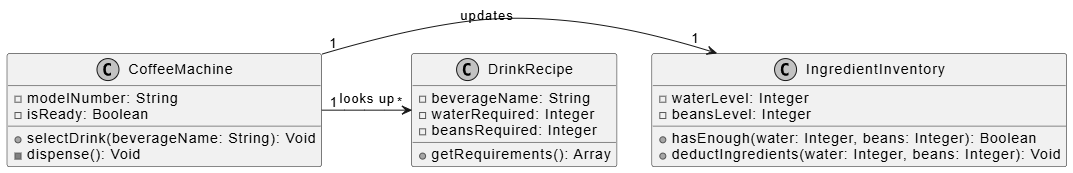
While sequence diagrams capture dynamic behavior, the Design Class Diagram (DCD) establishes the static structure. By tracing the messages sent in the sequence diagram, developers can directly map out the exact methods, attributes, and visibility modifiers required in the final codebase.
For instance, because the selectDrink() message is directed at the CoffeeMachine, the corresponding class must expose a selectDrink() method. The DCD serves as the final technical blueprint before implementation begins.
@startuml
skinparam monochrome true
hide empty members

class CoffeeMachine {
  - modelNumber: String
  - isReady: Boolean
  + selectDrink(beverageName: String): Void
  - dispense(): Void
}

class DrinkRecipe {
  - beverageName: String
  - waterRequired: Integer
  - beansRequired: Integer
  + getRequirements(): Array
}

class IngredientInventory {
  - waterLevel: Integer
  - beansLevel: Integer
  + hasEnough(water: Integer, beans: Integer): Boolean
  + deductIngredients(water: Integer, beans: Integer): Void
}

CoffeeMachine "1" -> "1" IngredientInventory : updates
CoffeeMachine "1" -> "*" DrinkRecipe : looks up
@endum
OOA/D Workflow Summary
The progression from abstract requirements to concrete software architecture ensures that every technical decision traces back to a validated business need.
| Artifact | Purpose | View Type | Focus |
|---|---|---|---|
| Use Case | Understand user goals and system boundaries. | Textual Stories | Requirements |
| Domain Model | Visualize real-world concepts and relationships. | Static (Conceptual) | Real-World Domain |
| Sequence Diagram | Map out how software components talk to each other. | Dynamic (Behavioral) | Software Collaboration |
| Design Class Diagram | Blueprint showing exact attributes and code methods. | Static (Software) | Software Structure |
Conclusion
Object-Oriented Analysis and Design is not merely a set of diagramming techniques; it is a disciplined framework for managing complexity. By systematically progressing from user-driven Use Cases through a conceptual Domain Model, into dynamic Sequence Diagrams, and finally crystallizing into precise Design Class Diagrams, engineering teams can dramatically reduce technical debt and misalignment.
The Automated Coffee Maker case study demonstrates that when software architecture mirrors real-world logic, developers spend less time deciphering abstract code and more time building robust, scalable features. As systems grow in complexity, adhering to these foundational OOA/D principles remains the most reliable strategy for delivering software that is intuitive to build, effortless to maintain, and perfectly aligned with the needs it was designed to serve.
This post is also available in Deutsche, Español, فارسی, Français, English, Bahasa Indonesia, 日本語, Polski, Portuguese, Ру́сский, Việt Nam, 简体中文 and 繁體中文.
