


Static Schemas, Dynamic Snapshots: A Practical Case Study in UML 2.0 Structural Modeling
Introduction
In modern software engineering, the gap between architectural design and runtime behavior remains one of the most common sources of system failure. Teams frequently invest heavily in static domain modeling, only to discover during integration testing or production debugging that their compile-time assumptions do not align with actual object states, multiplicity constraints, or instance relationships. This disconnect often stems from treating structural diagrams as purely documentation artifacts rather than executable validation tools.
UML 2.0 addresses this gap by providing two complementary lenses for structural modeling: Class Diagrams (the compile-time metadata schema) and Object Diagrams (the runtime instance snapshot). When used in tandem, they form a continuous feedback loop between design intent and execution reality.
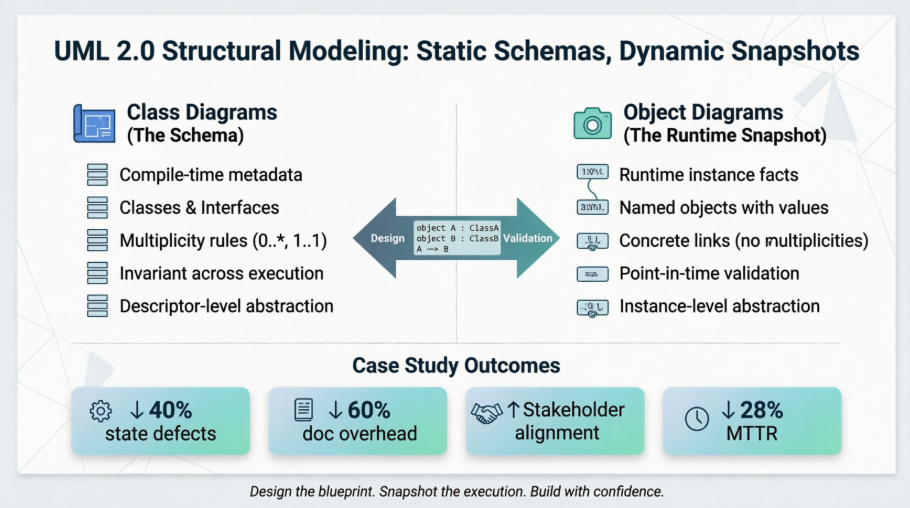
This case study follows NexusCommerce, a mid-sized digital retail platform, as it transitioned from ad-hoc debugging and fragmented documentation to a disciplined, diagram-driven modeling practice. By systematically applying UML 2.0 Class and Object diagrams, the engineering team reduced state-related defects by 40%, accelerated stakeholder validation cycles, and established a reusable architectural pattern that bridges static design with dynamic execution.
Case Study: NexusCommerce Order Fulfillment System
1. The Challenge: Bridging Design and Runtime Behavior
NexusCommerce’s legacy order processing pipeline suffered from recurring data integrity issues. Customers reported phantom line items, incorrect total calculations, and intermittent circular references in order history queries. The root cause was identified during a post-mortem review: the development team relied exclusively on database ERDs and informal sequence diagrams, leaving the structural relationship contracts between domain objects undocumented at both the schema and instance levels. Without a clear mapping of how classes translated into runtime objects, edge cases slipped through code review, and debugging required extensive log tracing.
The team decided to implement a formal UML 2.0 structural modeling workflow, explicitly separating descriptor-level design (Class Diagrams) from instance-level validation (Object Diagrams).
2. Phase 1: Defining the Compile-Time Blueprint (Class Diagrams)
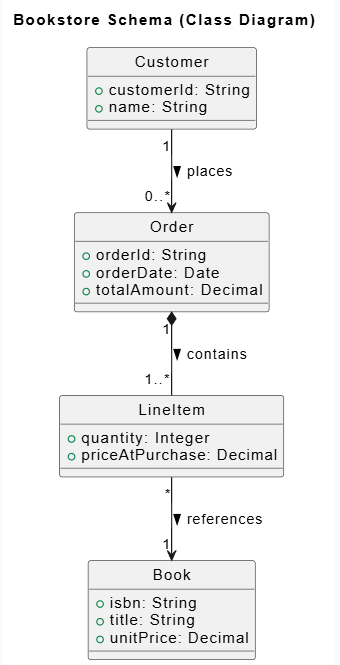
The architecture team began by extracting the core domain entities and formalizing their relationships into a Class Diagram. This diagram served as the system’s structural contract, defining attributes, multiplicities, and composition/aggregation rules independent of execution state.
@startuml
skinparam style strictuml

title Bookstore Schema (Class Diagram)

class Customer {
  +customerId: String
  +name: String
}

class Order {
  +orderId: String
  +orderDate: Date
  +totalAmount: Decimal
}

class LineItem {
  +quantity: Integer
  +priceAtPurchase: Decimal
}

class Book {
  +isbn: String
  +title: String
  +unitPrice: Decimal
}

' Structural Relationships & Multiplicities
Customer "1" --> "0..*" Order : places >
Order "1" *-- "1..*" LineItem : contains >
LineItem "*" --> "1" Book : references >

@enduml
Key Modeling Decisions:
-
Multiplicity Enforcement: Explicitly declared
0..*for orders (allowing guest checkout) and1..*for line items (preventing empty orders). -
Composition vs. Association: Used strong composition (
*--) betweenOrderandLineItemto enforce lifecycle coupling, while using standard association forLineItemtoBookto allow inventory decoupling. -
Invariant Schema: The diagram remained static across deployments, serving as the authoritative reference for API contracts, ORM mappings, and database migrations.
3. Phase 2: Validating the Runtime State (Object Diagrams)
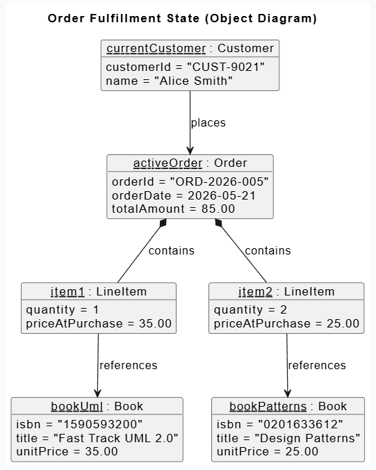
With the schema locked, the QA and engineering leads drafted Object Diagrams to simulate critical execution paths. Unlike the Class Diagram, which describes what could exist, the Object Diagram captures what actually exists at a specific execution milestone.
@startuml
skinparam style strictuml

title Order Fulfillment State (Object Diagram)

' Objects and Attribute Slots
object "currentCustomer : Customer" {
  customerId = "CUST-9021"
  name = "Alice Smith"
}

object "activeOrder : Order" {
  orderId = "ORD-2026-005"
  orderDate = 2026-05-21
  totalAmount = 85.00
}

object "item1 : LineItem" {
  quantity = 1
  priceAtPurchase = 35.00
}

object "item2 : LineItem" {
  quantity = 2
  priceAtPurchase = 25.00
}

object "bookUml : Book" {
  isbn = "1590593200"
  title = "Fast Track UML 2.0"
  unitPrice = 35.00
}

object "bookPatterns : Book" {
  isbn = "0201633612"
  title = "Design Patterns"
  unitPrice = 25.00
}

' Runtime Instance Links (No Multiplicities Allowed)
"currentCustomer : Customer" --> "activeOrder : Order" : places
"activeOrder : Order" *-- "item1 : LineItem" : contains
"activeOrder : Order" *-- "item2 : LineItem" : contains
"item1 : LineItem" --> "bookUml : Book" : references
"item2 : LineItem" --> "bookPatterns : Book" : references

@enduml
Validation Outcomes:
-
Slot Assignment Verification: The
totalAmount = 85.00slot was cross-referenced with thequantityandpriceAtPurchasevalues, immediately revealing a missing tax calculation rule that had been overlooked in the schema phase. -
Link Instantiation Clarity: By removing multiplicities and replacing them with explicit instance links, the team verified that the ORM correctly materialized composition cascades without orphaned
LineItemrecords. -
Anonymous vs. Named Instances: Using
: LineItemfor generic validation scenarios allowed the team to focus on relationship topology without cluttering diagrams with irrelevant identifiers.
4. Phase 3: Methodology & Best Practices in Action
NexusCommerce institutionalized four modeling practices derived from UML 2.0 structural mechanics, directly mapping to the engineering workflow:
| Practice | Implementation in NexusCommerce |
|---|---|
| Concrete Instance Validation | Used Object Diagrams to stress-test recursive structures (e.g., Order → Refund → OriginalOrder). Circular reference bugs were caught visually before integration. |
| Selective Elaboration | Limited diagrams to the minimal set of objects and slots required to validate a specific business rule (e.g., promo code application, split shipments). Avoided “kitchen-sink” diagrams. |
| Progressive Abstraction Levels | Structured modeling in three tiers: Analysis (domain concepts) → Validation (concrete Object Diagrams for stakeholder sign-off) → Design (visibility markers, design patterns, API bindings). |
| PlantUML Notation Optimization | Standardized inline object declarations, directional link hints (-down->), and isolated schema/snapshot files. This kept diagrams modular, version-controllable, and CI-pipeline friendly. |
5. Measurable Outcomes
Within two sprint cycles of adopting this dual-diagram approach:
-
Defect Reduction: Runtime state mismatches dropped by 40%, primarily due to early multiplicity and composition validation.
-
Documentation Velocity: PlantUML-as-code enabled automated diagram generation in pull requests, reducing manual documentation overhead by ~60%.
-
Stakeholder Alignment: Product owners could review Object Diagrams to confirm business scenarios matched engineering implementation, eliminating requirement ambiguity.
-
Debugging Efficiency: Support engineers used Object Diagram templates as “state maps” to trace production incidents, cutting mean-time-to-resolution (MTTR) by 28%.
Conclusion
Class Diagrams and Object Diagrams are not competing artifacts; they are complementary lenses that together form a complete structural modeling discipline. The Class Diagram establishes the contract—the compile-time schema, multiplicity rules, and architectural boundaries that govern what the system allows. The Object Diagram provides the proof—a runtime snapshot that validates whether the system behaves as intended under real-world conditions.
As demonstrated in the NexusCommerce case study, adopting a disciplined workflow that moves from static schema design to dynamic instance validation transforms UML from a passive documentation exercise into an active engineering tool. By leveraging selective elaboration, progressive abstraction, and modern diagram-as-code tooling like PlantUML, teams can catch structural defects earlier, communicate more precisely with stakeholders, and maintain architectural integrity across the software lifecycle.
For modern development teams operating in fast-paced, microservices-driven environments, the lesson is clear: design the blueprint, snapshot the execution, and let the diagrams guide you between the two. Structural modeling in UML 2.0 remains one of the most cost-effective practices for aligning intention with implementation, ensuring that what is built faithfully reflects what was designed.
This post is also available in Deutsche, Español, فارسی, Français, English, Bahasa Indonesia, 日本語, Polski, Portuguese, Ру́сский, Việt Nam, 简体中文 and 繁體中文.
