


Beyond Pretty Pictures: A Modern Guide to Analysis and Design with AI, Diagram-as-Code, and Visual Paradigm
Introduction
In the fast-paced world of software development, there’s a persistent myth that diagrams are merely decorative artifacts—”pretty pictures” that distract from the real work of writing code. This perspective overlooks a fundamental truth: software development is as much about communication and understanding as it is about implementation.

The Unified Modeling Language (UML) and related modeling techniques serve as critical bridges between abstract ideas and concrete implementations. They help teams navigate complexity, align stakeholders, and build systems that truly meet user needs. However, the landscape of analysis and design has evolved significantly since traditional UML practices were first established.
Today, we stand at the intersection of three transformative forces:
-
Artificial Intelligence – Automating diagram generation, suggesting design patterns, and validating models
-
Diagram-as-Code – Treating diagrams as version-controlled, collaborative artifacts integrated into development workflows
-
Modern Tooling – Platforms like Visual Paradigm that combine visual modeling with code integration and team collaboration
This guide explores why analysis and design remain essential, how traditional UML techniques provide value, and how modern approaches enhance these practices for today’s distributed, agile teams. Whether you’re a seasoned architect or a product manager looking to bridge the gap between business requirements and technical implementation, this comprehensive resource will help you leverage modeling effectively in the AI era.
Why Do Analysis and Design?
When it comes down to it, the real point of software development is cutting code. Diagrams are, after all, just pretty pictures. No user is going to thank you for pretty pictures; what a user wants is software that executes.
So when you are considering using the UML, it is important to ask yourself why you are doing it and how it will help you when it comes down to writing the code. There’s no proper empirical evidence to prove that these techniques are good or bad, but the following subsections discuss the reasons that I often come across for using them.
1. Communication: The Primary Purpose of UML
The fundamental reason to use the UML involves communication. I use the UML because it allows me to communicate certain concepts more clearly than the alternatives. Natural language is too imprecise and gets tangled when it comes to more complex concepts. Code is precise but too detailed. So I use the UML when I want a certain amount of precision but I don’t want to get lost in details. That doesn’t mean I avoid details; rather, I use the UML to highlight important details.
Practical Application for Consultants and Teams
As a consultant, I often have to breeze into a complex project and look intelligent in a very short period of time. I find the UML invaluable for that because it helps me acquire an overall view of the system. A look at a class diagram can quickly tell me what kinds of abstractions are present in the system and where the questionable parts are that need further work. As I probe deeper, I want to see how classes collaborate, so I ask to see interaction diagrams that illustrate key behaviors in the system.
If this is useful to me as an outsider, it is just as useful to the regular project team. It’s easy to lose sight of the forest for the trees on a large project. With a few choice diagrams in hand, you can find your way around the software much more easily.
Building a System Roadmap
To build a road map of a large system, use package diagrams to show the major parts of a system and their interdependencies. For each package, you can then draw a class diagram. When you draw a class diagram in this context, take a specification perspective. It is very important to hide implementations with this kind of work. You should also draw interaction diagrams for the key interactions in the package.
Use patterns to describe the important ideas in the system that appear in multiple places. Patterns help you to explain why your design is the way it is. It is also useful to describe designs you have rejected and why you rejected them. I always end up forgetting that kind of decision.
Key Principle: When you follow these guidelines, keep the results brief. An important part of communication is in highlighting the important things to say. You don’t have to show every feature of every class; you should instead show the important details. A brief document communicates much better than a thick one; the art is knowing what to leave out.
2. Learning Object-Oriented Design
A lot of people talk about the learning curve associated with OO—the infamous paradigm shift. In some ways, the switch to OO is easy. In other ways, there are a number of obstacles to working with objects, particularly in using them to their best advantage.
It’s not that it is difficult to learn how to program in an OO language. The problem is that it takes a while to learn to exploit the advantages that object languages provide. Tom Hadfield puts it well: Object languages allow advantages but don’t provide them. To use these advantages, you have to make the infamous paradigm shift. (Just make sure you are sitting down at the time!)
The techniques in the UML were to some degree designed to help people do good OO, but different techniques have different advantages.
Essential Techniques for Mastering OO
CRC Cards (Class-Responsibility-Collaborator)
One of the most valuable techniques for learning OO is CRC cards, which are not part of the UML, although they can and should be used with it. They were designed primarily for teaching people to work with objects. As such, CRC cards are deliberately different from traditional design techniques. Their emphasis on responsibilities and their lack of complex notation make CRC cards particularly valuable.
Interaction Diagrams
Interaction diagrams are very useful because they make the message structure very explicit and thus are useful for highlighting over-centralized designs, in which one object is doing all the work.
Class Diagrams
Class diagrams, used to illustrate class models, are both good and bad for learning objects. Class models are comfortably similar to data models; many of the principles that make for a good data model also make for a good class model. The major problem in using class diagrams is that it is easy to develop a class model that is data oriented rather than being responsibility oriented.
Design Patterns
The concept of patterns has become vital to learning OO because using patterns gets you to concentrate on good OO designs and to learn by following an example. Once you have gotten the hang of some basic modeling techniques, such as simple class diagrams and interaction diagrams, it is time to start looking at patterns.
Iterative Development
Another important technique is iterative development. This technique does not help you learn OO in any direct way, but it is the key to exploiting OO effectively. If you do iterative development from the start, you will learn, in context, the right kind of process and begin to see why designers suggest doing things the way they do.
Recommendation: When you start using a technique, you tend to do it by the book. My recommendation is to begin with the simple notations, particularly with class diagrams. As you get comfortable, you can pick up the more advanced ideas as you need them. You may also find that you wish to extend the method.
3. Communicating with Domain Experts
One of our biggest challenges in development is that of building the right system—one that meets users’ needs at a reasonable cost. This is made more difficult because we, with our jargon, have to communicate with users, who have their own, more arcane, jargon. (I did a lot of work in health care, and there the jargon isn’t even in English!) Achieving good communication, along with good understanding of the users’ world, is the key to developing good software.
Use Cases: The Bridge to User Needs
The obvious technique to use in addressing this is use cases. A use case is a snapshot of one aspect of your system. The sum of all use cases is the external picture of your system, which goes a long way toward explaining what the system will do.
A good collection of use cases is central to understanding what your users want. Use cases also present a good vehicle for project planning, because they control iterative development, which is itself a valuable technique, since it gives regular feedback to the users about where the software is going.
Conceptual Class Diagrams
Although use cases help with communication about surface things, it is also crucial to look at the deeper things. This involves learning how your domain experts understand their world.
Class diagrams can be extremely valuable here, as long as you draw them from the conceptual perspective. In other words, you should treat each class as a concept in a user’s mind. The class diagrams you draw are then not diagrams of data or of classes, but rather of the language of your users.
Activity Diagrams for Workflow
I have found activity diagrams to be very useful in cases in which workflow processes are an important part of the users’ world. Since they support parallel processes, activity diagrams can help you get away from unnecessary sequences. The way these diagrams deemphasize the links to classes, which can be a problem in later design, becomes an advantage during this more conceptual stage of the development process.
Modern Enhancements: AI, Diagram-as-Code, and Visual Paradigm
While traditional UML practices provide immense value, modern tooling and methodologies have transformed how we create, share, and maintain diagrams. Let’s explore how these innovations enhance the classic approaches described above.
AI-Powered Analysis and Design
Artificial intelligence is revolutionizing how we approach modeling:
1. Automated Diagram Generation
-
Code-to-Diagram: AI tools can analyze existing codebases and automatically generate class diagrams, sequence diagrams, and component diagrams, providing instant visibility into system architecture
-
Text-to-Diagram: Natural language descriptions of requirements can be converted into preliminary UML diagrams, accelerating the initial design phase
-
Pattern Recognition: AI can identify common design patterns in your code and suggest appropriate UML representations
2. Intelligent Design Validation
-
Anti-pattern Detection: AI can flag potential design issues, such as overly complex class hierarchies or circular dependencies
-
Consistency Checking: Automatically verify that diagrams align with implementation code and detect drift between design and reality
-
Best Practice Recommendations: Suggest improvements based on industry standards and proven architectural patterns
3. Enhanced Collaboration
-
Smart Suggestions: AI-powered assistants can recommend relevant diagrams based on the context of discussions
-
Automated Documentation: Generate narrative explanations of diagrams for stakeholders who may not be familiar with UML notation
-
Translation Services: Help bridge the gap between technical teams and domain experts by translating between technical and business terminology
Diagram-as-Code: Version Control for Visual Artifacts
The diagram-as-code approach treats diagrams as text-based artifacts that can be version controlled, reviewed, and integrated into CI/CD pipelines:
Benefits of Diagram-as-Code
-
Version Control Integration
-
Track changes to diagrams alongside code changes
-
Understand the evolution of system architecture over time
-
Branch and merge diagram modifications just like code
-
-
Collaborative Workflows
-
Code review processes apply to diagram changes
-
Pull requests for architectural modifications
-
Clear audit trails for design decisions
-
-
Automation and Consistency
-
Generate diagrams programmatically from specifications
-
Ensure consistency across related diagrams
-
Automate updates when underlying structures change
-
-
Popular Tools
-
PlantUML: Text-based UML diagramming
-
Mermaid: Markdown-friendly diagram syntax
-
Graphviz: General-purpose graph visualization
- VPasCode: Multiple language engine supports all of the above.
-
Example: PlantUML Class Diagram
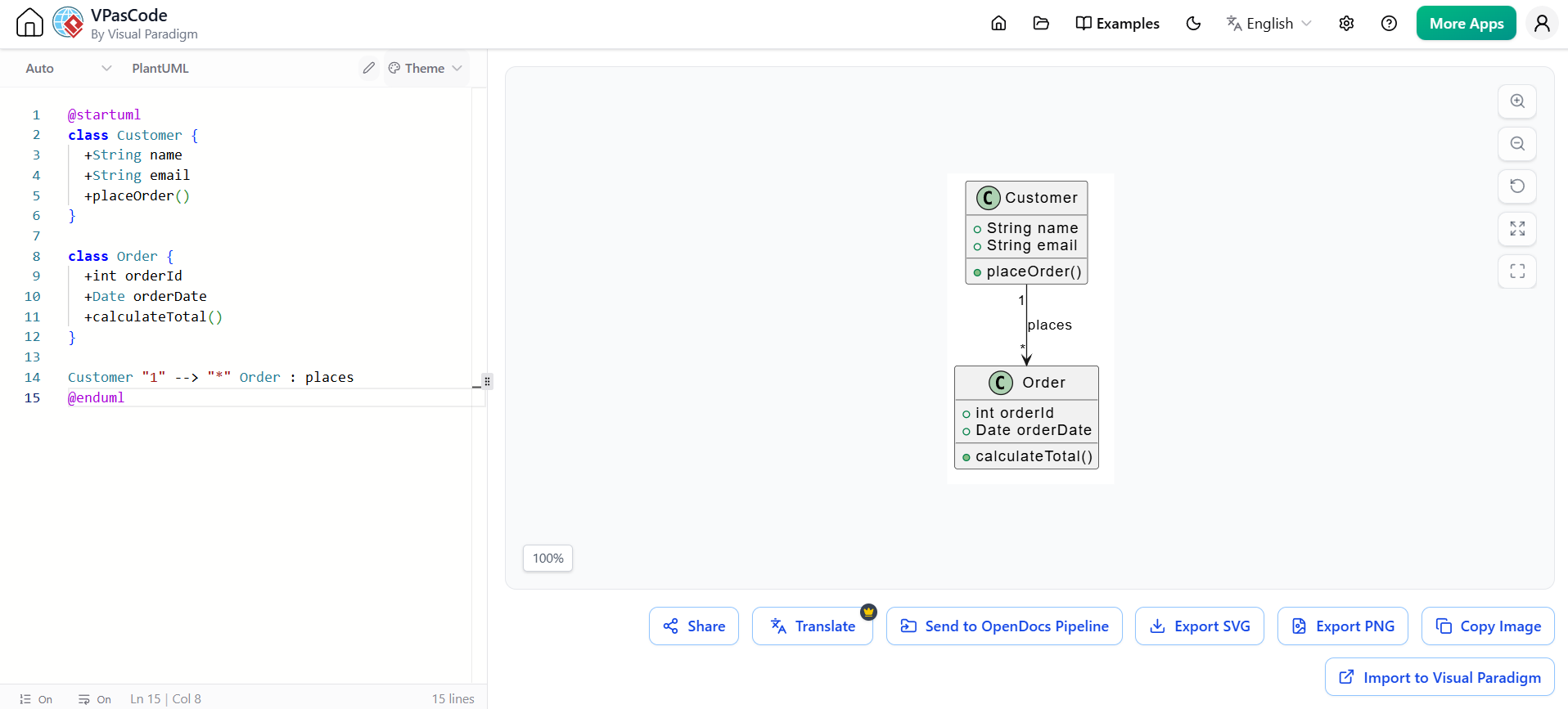
@startuml
class Customer {
  +String name
  +String email
  +placeOrder()
}

class Order {
  +int orderId
  +Date orderDate
  +calculateTotal()
}

Customer "1" --> "*" Order : places
@enduml
Visual Paradigm: Comprehensive Modeling Platform
Visual Paradigm represents a mature, enterprise-grade solution that combines traditional visual modeling with modern capabilities:
Key Features
-
Comprehensive UML Support
-
All 14 UML 2.x diagram types
-
SysML for systems engineering
-
BPMN for business process modeling
-
ERD for database design
-
-
Agile and DevOps Integration
-
Direct integration with Jira, Azure DevOps, and GitHub
-
Model-driven development capabilities
-
Round-trip engineering (code ↔ model synchronization)
-
-
Team Collaboration
-
Real-time collaborative editing
-
Comment and review workflows
-
Stakeholder-friendly presentation modes
-
-
AI-Assisted Modeling
-
Smart layout suggestions
-
Pattern recognition and application
-
Natural language to diagram conversion
-
-
Documentation Generation
-
Automatic report generation from models
-
Customizable templates
-
Export to multiple formats (PDF, Word, HTML)
-
Third-Party User Experience Sharing and Review
Visual Paradigm supports collaborative review processes that mirror modern code review practices:
-
Stakeholder Review Portals: Share diagrams with non-technical stakeholders through web-based viewers
-
Comment Threads: Contextual discussions tied to specific diagram elements
-
Approval Workflows: Formal sign-off processes for architectural decisions
-
Feedback Integration: Capture and track review comments directly within the modeling environment
-
Version Comparison: Visual diff tools to show changes between diagram versions
This approach ensures that diagrams serve their primary purpose—communication—by making them accessible and reviewable by all project participants, not just technical team members.
Practical Implementation Guide
Getting Started: A Phased Approach
Phase 1: Foundation (Weeks 1-2)
-
Start Simple: Begin with class diagrams and use cases
-
Choose Your Tool: Evaluate Visual Paradigm, PlantUML, or Mermaid based on team needs
-
Establish Conventions: Define naming standards, level of detail, and diagram scope
-
Train the Team: Conduct workshops on basic UML notation and modeling principles
Phase 2: Integration (Weeks 3-6)
-
Integrate with Workflow: Connect diagramming tools to your issue tracker and version control
-
Implement Review Process: Establish diagram review as part of your definition of done
-
Create Templates: Develop standard templates for common diagram types
-
Pilot Projects: Apply modeling to one or two active projects to refine practices
Phase 3: Optimization (Weeks 7-12)
-
Leverage AI Tools: Introduce AI-assisted diagram generation and validation
-
Adopt Diagram-as-Code: Migrate critical diagrams to text-based formats for better version control
-
Measure Impact: Track metrics like reduced rework, improved onboarding time, and stakeholder satisfaction
-
Continuous Improvement: Regularly refine practices based on team feedback
Best Practices for Effective Modeling
-
Purpose-Driven Diagrams
-
Every diagram should have a clear audience and purpose
-
Avoid creating diagrams “just because”
-
Delete or archive diagrams that no longer serve a purpose
-
-
Right Level of Abstraction
-
Match diagram detail to audience needs
-
Use multiple views for different stakeholders
-
Don’t try to capture everything in one diagram
-
-
Living Documentation
-
Keep diagrams synchronized with code
-
Update diagrams as part of development tasks
-
Use automation to reduce manual maintenance burden
-
-
Focus on Communication
-
Prioritize clarity over completeness
-
Use consistent notation and styling
-
Include brief narratives to explain complex diagrams
-
-
Iterative Refinement
-
Start with rough sketches and refine as understanding grows
-
Embrace changing diagrams as requirements evolve
-
Document rejected alternatives and reasoning
-
Conclusion
Analysis and design are not relics of waterfall methodologies—they are essential practices for building software that matters. The question is not whether to model, but how to model effectively in ways that enhance communication, accelerate learning, and ensure we build the right systems.
Traditional UML techniques provide a solid foundation for these activities. Class diagrams help us understand structure, interaction diagrams reveal behavior, use cases capture user needs, and activity diagrams model workflows. These tools, when applied thoughtfully, transform abstract requirements into actionable blueprints.
However, the modern software development landscape demands more than static diagrams stored in isolated repositories. The convergence of AI, diagram-as-code, and collaborative platforms like Visual Paradigm offers powerful enhancements:
-
AI reduces the friction of creating and maintaining diagrams, making modeling more accessible and less burdensome
-
Diagram-as-code brings diagrams into the same collaborative, version-controlled workflows as code, ensuring they remain relevant and accurate
-
Modern tooling facilitates third-party review and stakeholder engagement, fulfilling the primary purpose of diagrams: communication
For product managers, architects, and development teams alike, the goal remains unchanged: build software that solves real problems for real users. Modeling is not an end in itself—it is a means to that end. By embracing both timeless principles and modern innovations, we can create diagrams that are not just pretty pictures, but powerful tools for understanding, alignment, and successful delivery.
The future of analysis and design is not about choosing between code and diagrams, but about integrating them seamlessly. It’s about leveraging AI to handle the mundane, using version control to maintain accuracy, and employing collaborative platforms to ensure everyone—from developers to domain experts—can contribute to and benefit from shared understanding.
Start small, stay focused on communication, and let your modeling practices evolve alongside your projects. The diagrams you create today are investments in clarity, alignment, and ultimately, better software.
Quick Reference: Diagram Selection Guide
| Goal | Recommended Diagram Type | Modern Enhancement |
|---|---|---|
| Understand system structure | Class Diagram | AI-generated from codebase |
| Explore object interactions | Sequence/Interaction Diagram | PlantUML version control |
| Capture user requirements | Use Case Diagram | Collaborative review in Visual Paradigm |
| Model business workflows | Activity Diagram | BPMN integration with execution engines |
| Show system components | Component/Package Diagram | Architecture-as-code with Structurizr |
| Teach OO concepts | CRC Cards | Digital whiteboard integration |
| Document design decisions | Pattern documentation | AI-suggested patterns with rationale |
This guide synthesizes timeless modeling principles with contemporary practices. Whether you’re working in a startup or an enterprise, the combination of clear thinking, appropriate tooling, and modern collaboration methods will help you create diagrams that truly add value to your software development process.
