




Bridging the Gap: A Beginner’s Guide to Use Case Driven Architecture with Visual Paradigm AI
Introduction
Have you ever started a software project with a brilliant idea, only to find that six months later, your code looks nothing like your original design documents? This is one of the most common pain points in software development. Documentation becomes outdated, developers lose sight of the original business goals, and the final product fails to deliver real value.
Enter Use Case Driven Architecture (UCDA).
UCDA is a methodology that ensures your software design remains strictly aligned with business value from day one. By structuring your design into four sequential levels, you create a seamless bridge between initial business requirements, executable code, and self-documenting systems.
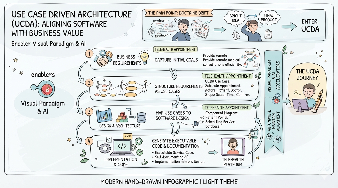
In this comprehensive tutorial, we will walk through these four levels using a realistic example: building a Telehealth Appointment Platform. We will also explore how to leverage Visual Paradigm and its AI features to automate the heavy lifting, making architecture accessible even for beginners.
Recommended Tooling: Visual Paradigm & AI
Before we dive in, let’s set up our workspace. While you can draw diagrams on a whiteboard, modern architecture requires synchronized, intelligent tooling.
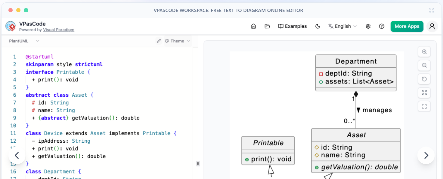
Visual Paradigm (VP) is highly recommended for this workflow. Its standout feature is the Visual Paradigm AI, which acts as your intelligent co-pilot. Instead of manually dragging and dropping shapes, you can use natural language to generate diagrams, ensure element consistency across different views, and map designs directly to code.
Level 1: Context (The Business & User View)
The Context level is your “30,000-foot view.” It defines the boundaries of your system. It answers three critical questions: Who is using the system? What are they trying to achieve? What external systems do we need to talk to?
Key Concepts
-
System Boundary: A clear line separating what your team builds (inside) from what you rely on (outside).
-
Actors: Human users or external systems interacting with your app.
-
Use Cases: Specific, measurable business goals (e.g., “Book Appointment,” not just “Click button”).
Realistic Example: Telehealth Context
Let’s map out the high-level view of our Telehealth platform.
PlantUML Implementation
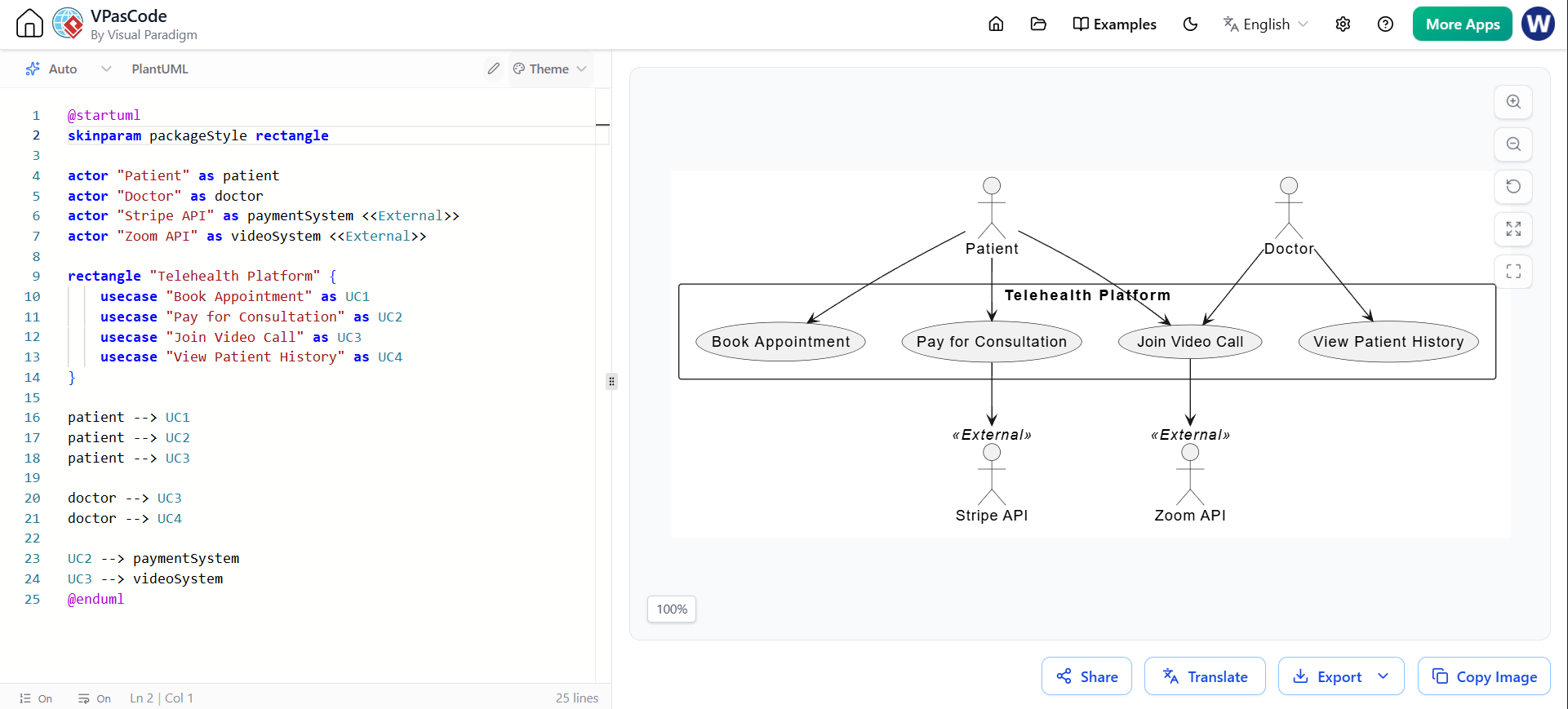
@startuml
skinparam packageStyle rectangle

actor "Patient" as patient
actor "Doctor" as doctor
actor "Stripe API" as paymentSystem <<External>>
actor "Zoom API" as videoSystem <<External>>

rectangle "Telehealth Platform" {
    usecase "Book Appointment" as UC1
    usecase "Pay for Consultation" as UC2
    usecase "Join Video Call" as UC3
    usecase "View Patient History" as UC4
}

patient --> UC1
patient --> UC2
patient --> UC3

doctor --> UC3
doctor --> UC4

UC2 --> paymentSystem
UC3 --> videoSystem
@enduml
🛠️ Visual Paradigm AI Integration
-
AI Generation: Open the VP AI chatbot and prompt: “Generate a system context diagram for a Telehealth platform including patients, doctors, Stripe for payments, and Zoom for video calls.”
-
Model Repository: Save these elements into the VP Model Repository. This ensures that when you use the “Patient” actor in Level 2, it links back to this exact same entity, preventing naming inconsistencies.
Level 2: Realization (The Interaction View)
Now we zoom in. Realization breaks open a specific use case to show the step-by-step collaboration between software components. We use the Boundary-Control-Entity (BCE) pattern to keep things organized:
-
Boundary: Handles user interaction (UI).
-
Control: Contains the business logic and rules.
-
Entity: Manages the data.
Realistic Example: Booking an Appointment
Let’s trace the “Book Appointment” use case to see how the Patient interacts with the system.
PlantUML Implementation
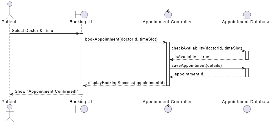
@startuml
actor Patient
boundary "Booking UI" as UI
control "Appointment Controller" as Controller
entity "Appointment Database" as DB

Patient -> UI : Select Doctor & Time
activate UI

UI -> Controller : bookAppointment(doctorId, timeSlot)
activate Controller

Controller -> DB : checkAvailability(doctorId, timeSlot)
activate DB
DB --> Controller : isAvailable = true
deactivate DB

Controller -> DB : saveAppointment(details)
activate DB
DB --> Controller : appointmentId
deactivate DB

Controller --> UI : displayBookingSuccess(appointmentId)
deactivate Controller

UI --> Patient : Show "Appointment Confirmed!"
deactivate UI
@enduml
Level 3: Design (The Code Blueprint View)
Level 3 translates the behavioral steps from Level 2 into a static structural blueprint. This is the exact map developers use to write code. It defines the classes, interfaces, and how they connect.
Realistic Example: The Appointment Blueprint
Based on our sequence diagram, we need an interface for the service, a controller to handle the web requests, and an entity to hold the data.
PlantUML Implementation
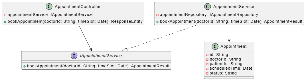
@startuml
interface IAppointmentService {
    + bookAppointment(doctorId: String, timeSlot: Date): AppointmentResult
}

class AppointmentController {
    - appointmentService: IAppointmentService
    + bookAppointment(doctorId: String, timeSlot: Date): ResponseEntity
}

class AppointmentService {
    - appointmentRepository: IAppointmentRepository
    + bookAppointment(doctorId: String, timeSlot: Date): AppointmentResult
}

class Appointment {
    - id: String
    - doctorId: String
    - patientId: String
    - scheduledTime: Date
    - status: String
}

AppointmentController --> IAppointmentService
AppointmentService ..|> IAppointmentService
AppointmentService --> Appointment
@enduml
🛠️ Visual Paradigm AI Integration
-
Class Generation: Use Visual Paradigm AI to generate these class structures directly from the Level 2 sequence paths. It automatically identifies the nouns (Entities) and verbs (Methods).
-
ORM Mapping: Use the VP Ecosystem to map the
Appointmentclass directly to a relational database schema (ERD) or generate Hibernate/Entity Framework configurations automatically.
Level 4: Execution & Living Doc (The Synchronized Reality)
This is where the magic happens. Level 4 ensures that your architecture doesn’t die in a PDF file. It transforms your static diagrams into executable code and auto-updating documentation.
Key Concepts
-
Forward Engineering: Generating skeletal code files directly from your Class Diagrams.
-
Reverse Engineering: Scanning your modified code to automatically update your architectural models.
-
Living Documentation: Architecture documents that regenerate on every CI/CD commit, ensuring diagrams never go out of date.
Code Implementation
Using the Level 3 blueprint, a developer writes the actual Java code. Notice how perfectly it matches the diagram:
@RestController
@RequestMapping("/api/appointments")
public class AppointmentController {

    private final IAppointmentService appointmentService;

    // Constructor injection based on our design blueprint
    public AppointmentController(IAppointmentService appointmentService) {
        this.appointmentService = appointmentService;
    }

    @PostMapping("/book")
    public ResponseEntity<AppointmentResult> bookAppointment(
            @RequestParam String doctorId,
            @RequestParam Date timeSlot) {

        // Delegating to the service layer as defined in the sequence diagram
        AppointmentResult result = appointmentService.bookAppointment(doctorId, timeSlot);
        return ResponseEntity.ok(result);
    }
}
🛠️ Tooling Integration: OpenDocs
- Living Docs: Integrate OpenDocs directly into your CI/CD pipeline to automate documentation generation. By utilizing standardized code annotations (such as OpenAPI/Swagger) within your
AppointmentController, OpenDocs scans your codebase on every commit. It automatically generates and publishes up-to-date API specifications and system summaries. Your documentation becomes a true “living” reflection of your codebase, ensuring that developers and stakeholders always interact with the current system reality without the need for manual diagram updates.
Conclusion
Building software is complex, but managing that complexity doesn’t have to be. By adopting a Use Case Driven Architecture, you ensure that every line of code you write traces back to a specific, valuable business goal.
As we’ve seen, the journey from a high-level business idea to executable code is much smoother when broken down into four distinct levels:
-
Context: Defining the boundaries and actors.
-
Realization: Mapping the step-by-step interactions.
-
Design: Creating the structural code blueprint.
-
Execution: Keeping code and documentation perfectly in sync.
By leveraging modern tooling like Visual Paradigm and its AI features, beginners and veterans alike can automate the tedious parts of modeling. You no longer have to choose between moving fast and maintaining good documentation—you can do both.
Your Next Step: Download Visual Paradigm, open the AI assistant, and try generating a Context diagram for a project you are currently working on. Watch how quickly your architectural vision comes to life!
This post is also available in Deutsche, Español, فارسی, Français, English, Bahasa Indonesia, 日本語, Polski, Portuguese, Ру́сский, Việt Nam, 简体中文 and 繁體中文.
