




Guide to the Visual Paradigm Ecosystem
Visual Paradigm’s ecosystem provides an integrated environment for moving from early ideas to validated software architectures, executable specifications, implementation planning, and continuously updated technical documentation.
Its central strength is the connection between traditional desktop modeling, browser-based Diagram-as-Code workflows, AI-assisted generation, cloud repositories, and living documentation. Teams can begin with an informal requirement, transform it into diagrams or structured models, refine it using enterprise-grade tools, and publish the results without repeatedly exporting and re-importing static files.
1. Ecosystem Overview
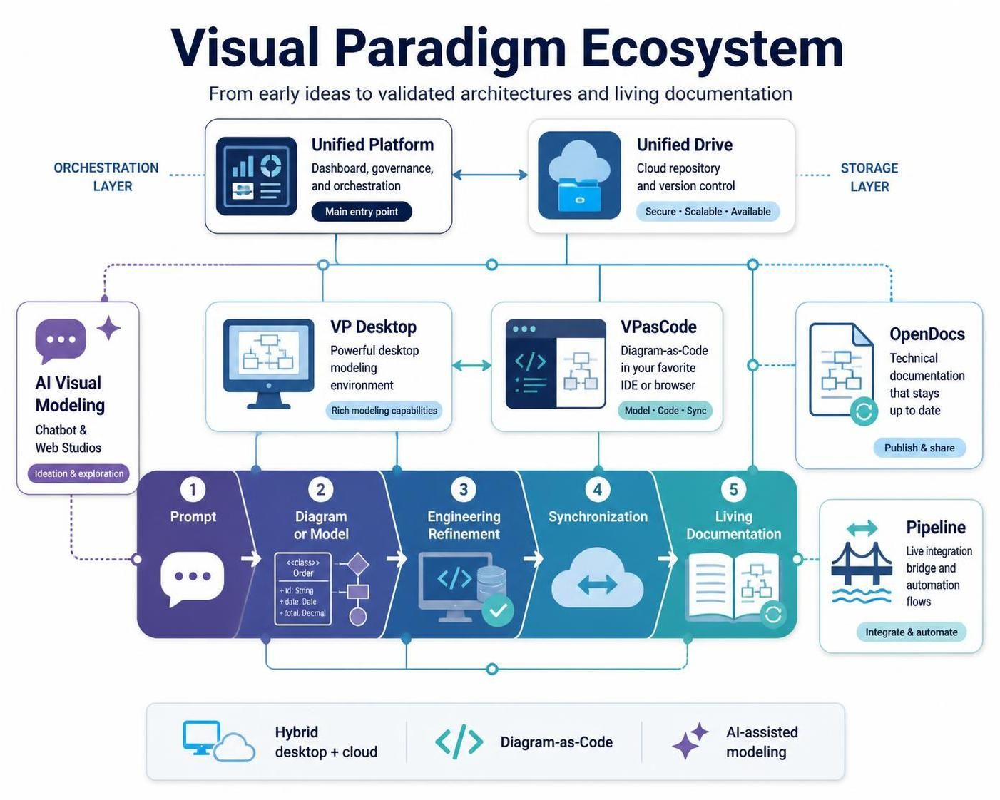
The ecosystem is organized around several specialized components connected through a centralized orchestration layer:
-
Unified Platform — The main entry point for accessing tools, projects, repositories, and shared assets.
-
Unified Drive — A centralized, drive-like repository for storing and indexing project artifacts.
-
VP Desktop — A powerful local application for detailed enterprise modeling and engineering work.
-
VPasCode — A browser-based Diagram-as-Code platform for text-driven diagram creation and version-controlled architecture.
-
AI Visual Modeling Chatbot and Web Studios — Prompt-driven tools for turning natural-language descriptions into diagrams, models, and workflows.
-
OpenDocs — A documentation environment for creating structured technical specifications.
-
Pipeline — A live integration mechanism that connects source models and diagrams to published documents.
Together, these components support a lifecycle that can be summarized as:
Prompt → Diagram or Model → Engineering Refinement → Synchronization → Living Documentation
2. The Unified Platform
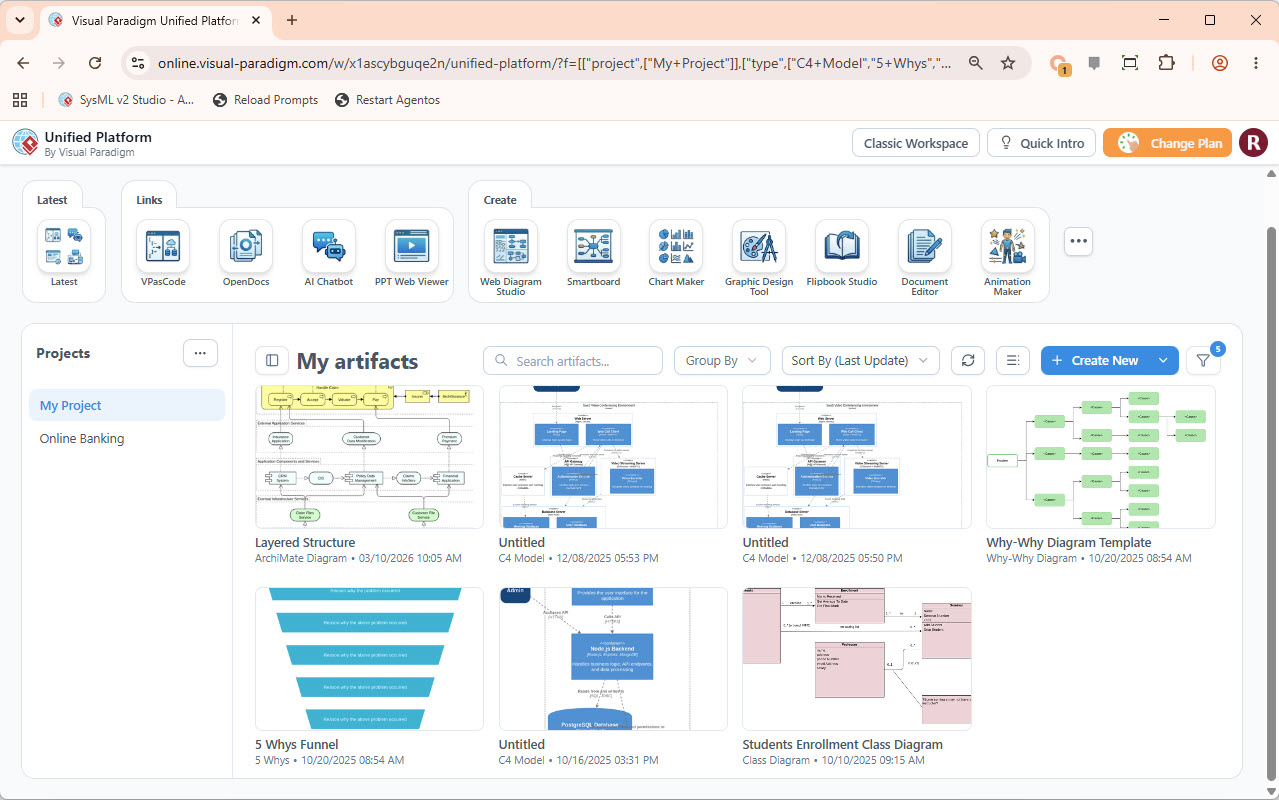
The Unified Platform acts as the ecosystem’s primary dashboard and “front door.” Rather than requiring users to open each application independently, it provides a central place to navigate projects, launch specialized tools, and access shared resources.
Main responsibilities
The Unified Platform is used to:
-
Organize projects and workspaces
-
Launch VP Desktop, VPasCode, AI tools, and documentation tools
-
Provide access to shared repositories
-
Connect teams working across different modeling environments
-
Surface artifacts created in both cloud and local workspaces
-
Serve as the coordination point for the broader engineering workflow
It is particularly useful for organizations that need a common entry point for analysts, architects, developers, project managers, and technical writers.
3. Unified Drive
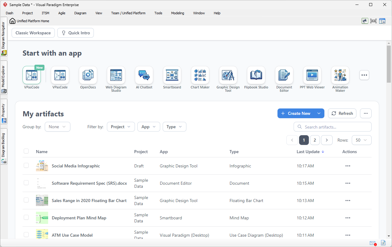
Unified Drive provides centralized storage and indexing for the ecosystem’s artifacts. It functions similarly to a shared project drive, but its purpose is to bring together diverse forms of engineering content.
Types of artifacts
A Unified Drive repository may contain:
-
Wireframes
-
Business models
-
User journeys
-
UML diagrams
-
BPMN process models
-
SysML models
-
Architecture diagrams
-
Database schemas
-
Code specifications
-
API documentation
-
Design documents
-
Technical specifications
-
AI-generated starting models
-
VPasCode source files
-
Published OpenDocs content
Because artifacts can originate in different tools, Unified Drive helps teams maintain a common project context instead of scattering files across disconnected locations.
Typical benefits
Unified Drive is most useful when:
-
Multiple roles contribute to the same system design
-
Projects contain both visual and text-based artifacts
-
Teams need to access models from cloud and local workspaces
-
Documentation must refer to current design assets
-
Architects and developers need a shared source of truth
4. VP Desktop
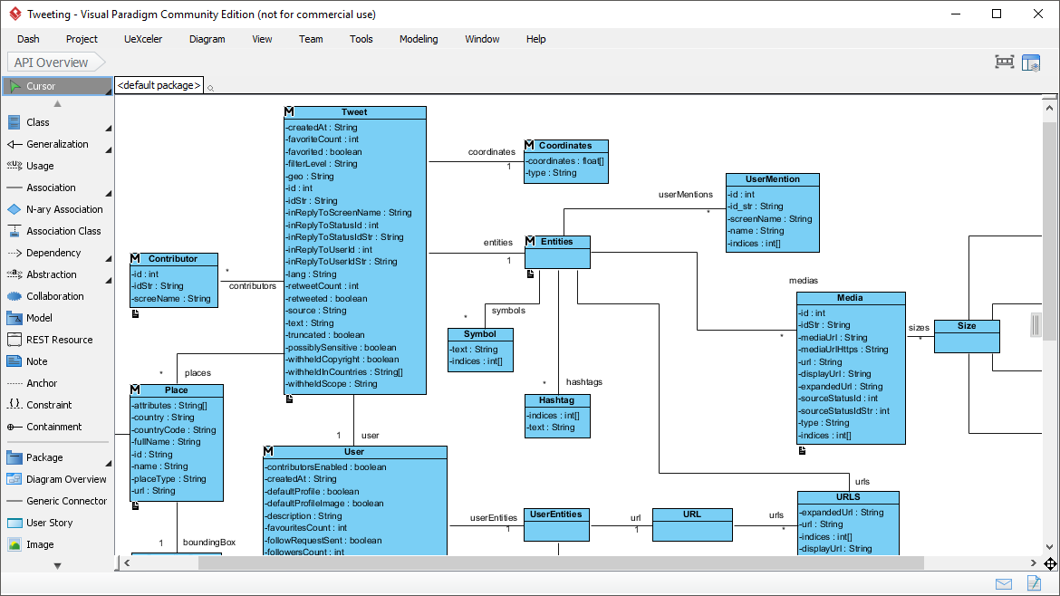
VP Desktop is the ecosystem’s heavyweight modeling and engineering application. It is intended for work that requires detailed structure, strict validation, large-scale model management, or close interaction with code and databases.
Primary capabilities
VP Desktop is suited to:
-
Complex enterprise modeling
-
UML modeling
-
SysML modeling
-
BPMN modeling
-
Large-scale architectural design
-
Object-oriented relationship mapping
-
Code reverse engineering
-
Code forward engineering
-
Database schema generation
-
Database and model synchronization
-
Detailed structural validation
-
Offline design work
-
Compliance checking against formal modeling standards
When to use VP Desktop
VP Desktop is the preferred choice when the task involves:
-
Large models with many interconnected elements
-
Detailed class, component, deployment, or data structures
-
Formal modeling notation
-
Engineering existing code into a model
-
Generating implementation structures from a model
-
Validating relationships and constraints
-
Working with enterprise-scale databases
-
Performing tasks locally without depending entirely on browser-based tools
Example
A development team designing an order-management system might use VP Desktop to model:
-
Customer, Order, Payment, and Shipment classes
-
Service and database dependencies
-
Deployment nodes
-
Message flows
-
Database tables and relationships
-
Interface contracts
-
Traceability between software components and business processes
The desktop environment is especially valuable after an initial idea has been generated, because it allows senior engineers and architects to add precision and enforce structural consistency.
5. VPasCode
VPasCode is a browser-based Diagram-as-Code platform. It allows users to create diagrams by writing structured text rather than manually drawing every element.
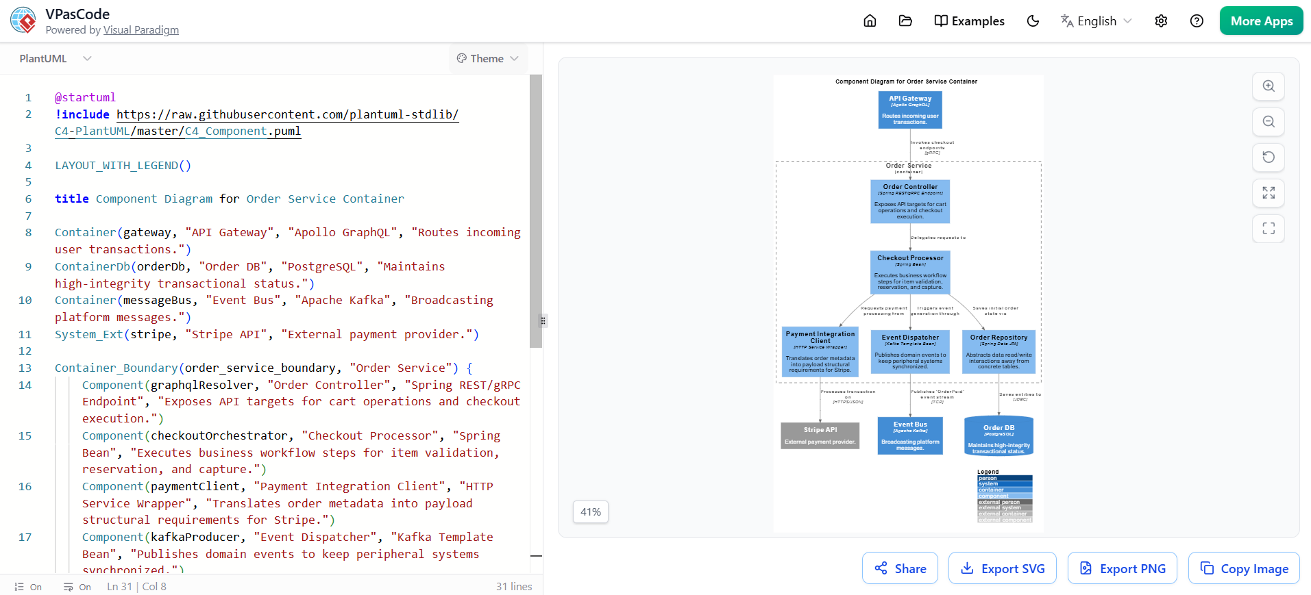
This approach treats diagrams as source-controlled artifacts, similar to software code or infrastructure definitions.
Supported content types
VPasCode can work with:
-
PlantUML
-
Mermaid.js
-
Graphviz
-
D2
-
Code schemas
-
JSON specifications
-
YAML specifications
Why use Diagram-as-Code?
Diagram-as-Code provides several advantages:
-
Diagrams can be stored in Git repositories
-
Changes can be reviewed as text diffs
-
Architecture can be updated alongside source code
-
Teams can automate diagram generation
-
Repeated diagram styles can be standardized
-
Text-based definitions are easier to reproduce
-
Developers can contribute without relying exclusively on graphical editors
Best use cases
VPasCode is particularly effective for:
-
Software architecture diagrams
-
API documentation
-
Microservice maps
-
C4 model diagrams
-
Sequence diagrams
-
Entity and relationship representations
-
Deployment views
-
System context diagrams
-
Documentation embedded in engineering repositories
-
Teams practicing documentation-as-code
Example workflow
A developer might define a service architecture using Mermaid or PlantUML, render the result in VPasCode, review the visual output, and commit the source definition to a version-control system. If the architecture changes, the text is updated and the diagram is regenerated.
This makes VPasCode a strong bridge between engineering repositories and visual communication.
6. AI Visual Modeling Chatbot and Web Studios
The AI Visual Modeling Chatbot and related Web Studios help users move from natural-language descriptions to structured visual or conceptual outputs.
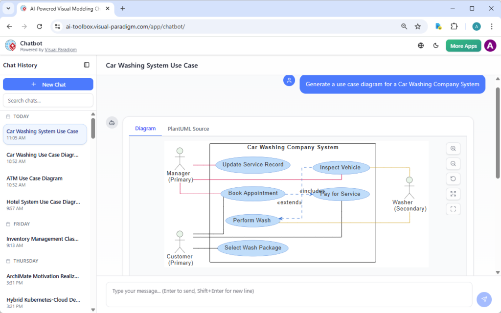
They are designed to reduce the friction of starting a model from a blank canvas.
Typical inputs
Users may provide descriptions such as:
-
“Design a microservice architecture for an online bookstore.”
-
“Create a user journey for account registration.”
-
“Model the interaction between a customer, payment service, and order service.”
-
“Generate a high-level system context diagram.”
-
“Describe the workflow for approving a loan application.”
The AI tools can then produce initial:
-
Architecture templates
-
Logic flows
-
Process models
-
User journeys
-
Relationship maps
-
Structural diagrams
-
Conceptual models
-
System interaction outlines
Best use cases
AI-assisted modeling is most valuable during:
-
Brainstorming
-
Early requirements analysis
-
Architecture exploration
-
Workshop preparation
-
Rapid prototyping
-
Stakeholder communication
-
Initial documentation
-
Converting informal notes into structured concepts
Recommended approach
AI-generated output should be treated as a starting point rather than a finished engineering model. A practical process is:
-
Describe the system in natural language.
-
Review the generated structure for missing or incorrect assumptions.
-
Move the result into VPasCode or VP Desktop.
-
Add formal relationships, attributes, constraints, and dependencies.
-
Validate the design with the appropriate engineering and modeling tools.
-
Publish the refined result through OpenDocs.
7. OpenDocs and Pipeline
OpenDocs is the ecosystem’s technical publishing and knowledge-management environment. It is intended for creating specifications and other structured documentation.
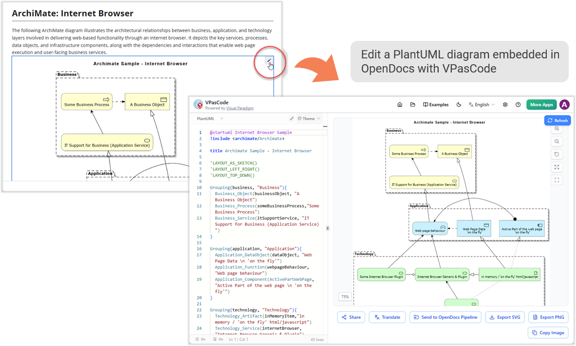
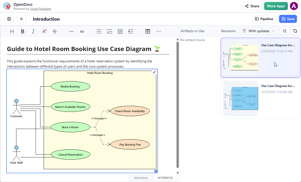
The Pipeline connects OpenDocs with source models and diagrams, allowing documents to contain live or interactive representations rather than static image exports.
OpenDocs use cases
OpenDocs can support:
-
Software Design Documents
-
Architecture specifications
-
API documentation
-
System requirements
-
Technical standards
-
Process documentation
-
Database specifications
-
Implementation guidance
-
Project knowledge bases
-
Design reviews
The role of Pipeline
Pipeline acts as a live data-transfer bridge between modeling tools and documentation.
Instead of exporting a diagram as a fixed image, a team can embed a model or diagram directly into a document. When the source artifact changes, the embedded content can be updated so that the document remains aligned with the current design.
Advantages over static exports
Static image exports often create synchronization problems:
-
The design changes but the document does not
-
Multiple image versions circulate
-
Authors must manually replace outdated diagrams
-
Reviewers cannot easily trace a diagram to its source
-
Documentation gradually diverges from implementation plans
Pipeline addresses these problems by connecting documentation to the originating model or diagram.
8. How the Components Work Together
Each component serves a distinct purpose, but the ecosystem is designed for movement between them.
| Component | Primary role | Best suited to |
|---|---|---|
| Unified Platform | Navigation and orchestration | Accessing tools, projects, and repositories |
| Unified Drive | Centralized artifact storage | Sharing and indexing project assets |
| AI Chatbot and Web Studios | Rapid generation | Turning requirements into initial models and flows |
| VPasCode | Diagram-as-Code | Text-driven, version-controlled architecture |
| VP Desktop | Detailed engineering | Formal modeling, code engineering, and validation |
| OpenDocs | Technical publishing | Creating structured specifications and knowledge bases |
| Pipeline | Live synchronization | Embedding current models into documents |
The choice of tool depends primarily on the maturity and complexity of the work.
-
Use AI tools when the idea is still informal.
-
Use VPasCode when the output should be text-based, reviewable, and version-controlled.
-
Use VP Desktop when the design requires rigorous modeling and engineering precision.
-
Use OpenDocs and Pipeline when the result must become maintainable technical documentation.
-
Use Unified Platform and Unified Drive to coordinate access and preserve project continuity.
9. End-to-End Workflow Example
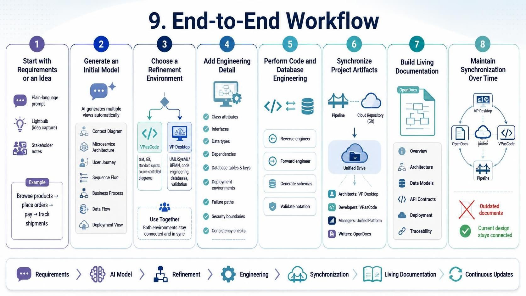
Step 1: Start with requirements or an idea
A project manager, analyst, architect, or developer begins with a plain-language description of the problem.
For example:
The system should allow customers to browse products, place orders, make payments, and track shipments. The architecture should use independently deployable services.
At this stage, the description may be incomplete. The objective is to establish an initial direction.
Step 2: Generate an initial model
The user opens the AI Visual Modeling Chatbot or a suitable Web Studio through the Unified Platform.
The prompt can request:
-
A system context diagram
-
A microservice architecture
-
A user journey
-
A sequence of service interactions
-
A business process
-
A data-flow model
-
A high-level deployment view
The generated output provides a first representation of the system and helps expose missing concepts or unclear relationships.
Step 3: Choose a refinement environment
After reviewing the generated output, the user selects the appropriate modeling destination.
Move to VPasCode when:
-
The diagram should be maintained as text
-
The project uses Git-based collaboration
-
Developers need to review diagram changes
-
The architecture is primarily represented through standard diagram syntax
-
The output will be maintained alongside source code
Move to VP Desktop when:
-
The model requires formal UML, SysML, or BPMN elements
-
The design includes many interconnected structures
-
Code must be reverse-engineered or generated
-
Database schemas must be designed or synchronized
-
Strict validation is required
-
The team needs detailed object-level modeling
In some projects, both tools may be used. VPasCode can represent high-level architecture while VP Desktop manages detailed enterprise models.
Step 4: Add engineering detail
Senior engineers and architects refine the initial design.
This may include:
-
Adding class attributes and operations
-
Defining interfaces
-
Assigning service responsibilities
-
Adding data types
-
Mapping dependencies
-
Specifying database tables
-
Defining keys and relationships
-
Connecting business processes to software components
-
Adding deployment environments
-
Modeling failure paths
-
Clarifying security and operational boundaries
-
Checking structural consistency
This step converts an approximate conceptual model into a design that can support implementation.
Step 5: Perform code and database engineering
When working in VP Desktop, the team can connect the model to implementation and data structures.
Typical activities include:
-
Reverse-engineering existing code into models
-
Forward-engineering model structures into code
-
Generating database schemas
-
Comparing design models with existing databases
-
Checking whether dependencies and relationships are valid
-
Refining class and component structures
-
Validating formal notation
This stage is important when the project must maintain alignment between conceptual design and technical implementation.
Step 6: Synchronize project artifacts
Once the design has been refined, the relevant diagrams and models are synchronized through the Pipeline and made available through Unified Drive.
This gives the broader team access to current design assets without requiring every participant to work in the same tool.
For example:
-
Architects may work in VP Desktop
-
Developers may maintain diagrams in VPasCode
-
Project managers may review outputs through the Unified Platform
-
Technical writers may access the artifacts through OpenDocs
Step 7: Build living documentation
Technical writers or engineers create a Software Design Document or related specification in OpenDocs.
The document may include:
-
System overview
-
Scope and assumptions
-
Architecture diagrams
-
Component descriptions
-
Data models
-
API contracts
-
Process flows
-
Deployment diagrams
-
Design decisions
-
Implementation notes
-
Traceability information
Using Pipeline, diagrams and models are embedded as connected artifacts instead of being inserted only as static images.
Step 8: Maintain synchronization over time
As the system evolves, changes made in VP Desktop or VPasCode can flow into the published documentation.
This reduces the risk that:
-
Architecture diagrams become obsolete
-
Design documents describe an earlier system version
-
Developers implement against outdated models
-
Reviewers see disconnected versions of the same artifact
The result is a documentation process that remains connected to the design lifecycle.
10. Example: Microservice Architecture Project
Consider a team designing an e-commerce platform.
Initial concept
The project manager describes the desired user journey:
-
A customer browses the catalog.
-
The customer adds products to a cart.
-
The customer submits an order.
-
The payment service authorizes payment.
-
The fulfillment service prepares the shipment.
-
The customer tracks delivery.
AI-assisted modeling
The AI Chatbot generates:
-
A customer journey
-
A system context diagram
-
Candidate microservices
-
A sequence of interactions
-
An initial data-flow model
The proposed services might include:
-
Catalog Service
-
Cart Service
-
Order Service
-
Payment Service
-
Fulfillment Service
-
Notification Service
-
Identity Service
VPasCode refinement
The architecture team moves the high-level design into VPasCode and expresses the service relationships using Diagram-as-Code.
This enables the team to:
-
Store the diagram with the project repository
-
Review architecture changes through text diffs
-
Regenerate the diagram after service changes
-
Produce consistent views for technical documentation
VP Desktop refinement
The engineering team then uses VP Desktop to model:
-
Domain classes
-
Service interfaces
-
Data entities
-
Database relationships
-
Deployment nodes
-
Dependencies among components
They also validate the model and refine the database structure.
OpenDocs publication
The final architecture is published in OpenDocs as part of a Software Design Document. Pipeline embeds the current architecture and data models so that later changes can be reflected in the document.
11. Collaboration Across Roles
The hybrid architecture supports different working styles without forcing every contributor into the same application.
| Role | Likely tools | Typical activities |
|---|---|---|
| Project manager | Unified Platform, AI Chatbot | Describe goals, generate initial flows, review progress |
| Business analyst | AI tools, VP Desktop, OpenDocs | Model requirements, processes, and user journeys |
| Software architect | VP Desktop, VPasCode | Design architecture, services, dependencies, and boundaries |
| Developer | VPasCode, VP Desktop | Maintain diagrams, review designs, connect models to code |
| Database engineer | VP Desktop | Design schemas, relationships, and synchronization mappings |
| Technical writer | OpenDocs, Pipeline | Assemble specifications and embed live design artifacts |
| Reviewer or stakeholder | Unified Platform, OpenDocs | Navigate projects and review current documentation |
This division allows each role to use the environment most appropriate for its responsibilities while preserving a connected project repository.
12. Selecting the Right Component
A simple decision process can help determine where to begin.
Choose the AI Chatbot or Web Studios if:
-
You have only a text description
-
You need to overcome a blank canvas
-
You want a quick architectural sketch
-
You are exploring multiple possible designs
-
You need to turn workshop notes into visual structures
Choose VPasCode if:
-
Your diagrams should be stored as text
-
Version control is important
-
Developers will maintain the architecture
-
You use PlantUML, Mermaid, Graphviz, or D2
-
The diagram belongs alongside source code or API definitions
Choose VP Desktop if:
-
You need enterprise-scale modeling
-
The design uses formal UML, SysML, or BPMN notation
-
You need database engineering
-
You need code reverse or forward engineering
-
You require detailed validation and traceability
Choose OpenDocs and Pipeline if:
-
You are producing a formal technical document
-
Diagrams must remain synchronized with their source
-
You want living Software Design Documents
-
Multiple teams need a shared technical reference
-
Static image exports are creating maintenance problems
Choose Unified Platform and Unified Drive if:
-
You need a central project workspace
-
Multiple tools are involved
-
Teams need a shared artifact repository
-
You need a single location for navigation and collaboration
13. Recommended Operating Practices
Treat AI output as a draft
AI-generated models are useful for acceleration, but they should be reviewed and refined by domain experts. Validate terminology, relationships, service boundaries, assumptions, and missing requirements before using the model as an engineering baseline.
Keep high-level and detailed views connected
Use VPasCode for readable architectural views and VP Desktop for detailed formal models when appropriate. The two levels serve different audiences and should complement each other rather than compete.
Store source definitions, not only rendered diagrams
For Diagram-as-Code work, preserve PlantUML, Mermaid, Graphviz, D2, JSON, or YAML source. Rendered images are useful for presentation, but source definitions are more maintainable and reviewable.
Use Unified Drive as a shared source of truth
Centralize important artifacts rather than allowing multiple disconnected copies to circulate through email, local folders, or separate document systems.
Publish through Pipeline
Whenever possible, connect documentation to live models and diagrams. This reduces the amount of manual replacement required when the architecture changes.
Separate exploration from validation
Early ideation should be fast and flexible. Formal validation should happen after the design has stabilized enough for detailed review. Using AI tools for exploration and VP Desktop for validation supports both speed and rigor.
Design documentation as part of the lifecycle
Documentation should not be treated as a final project deliverable created after implementation. By connecting OpenDocs to active models, the team can maintain documentation throughout design, development, and later change cycles.
14. Key Benefits
The ecosystem’s integrated approach provides several practical benefits:
-
Faster movement from ideas to visual models
-
Reduced friction between natural-language requirements and formal design
-
Support for both graphical and text-based modeling
-
Better collaboration between architects, developers, analysts, and writers
-
Stronger alignment between models, code, databases, and documentation
-
Version-control support for architecture diagrams
-
Formal validation for complex enterprise designs
-
Reduced dependence on static diagram exports
-
More consistent technical specifications
-
Improved traceability across the engineering lifecycle
Conclusion
Visual Paradigm’s ecosystem combines AI-assisted ideation, Diagram-as-Code, enterprise desktop modeling, centralized artifact management, and living documentation into a connected workflow.
The Unified Platform provides the entry point, Unified Drive organizes the project’s assets, AI tools accelerate early modeling, VPasCode supports text-driven and version-controlled diagrams, VP Desktop delivers detailed engineering and validation, and OpenDocs with Pipeline keeps technical documentation synchronized with its source models.
Used together, these components create a continuous path from informal requirements to formal architecture, implementation-ready models, and maintainable technical documentation.
This post is also available in Deutsche, Español, فارسی, Français, English, Bahasa Indonesia, 日本語, Polski, Portuguese, Ру́сский, Việt Nam and 简体中文.
